


| Issue |
JNWPU
Volume 44, Number 2, April 2026
|
|
|---|---|---|
| Page(s) | 363 - 370 | |
| DOI | https://doi.org/10.1051/jnwpu/20264420363 | |
| Published online | 12 June 2026 | |
Multi-scale simulation and verification test of vibration characteristics of lattice-structured air rudder made by additive manufacturing
增材制造点阵结构空气舵振动特性多尺度模拟与试验验证
China Aerodynamics Research and Development Center, Mianyang 621000, China
Received:
1
September
2025
Abstract
In order to grasp the vibration characteristics of a lattice-structured air rudder made by additive manufacturing, this paper carried out its multi-scale simulation and verification tests. Firstly, the design and additive manufacturing of the air rudder with the body-centered cubic lattice structure are conducted with the selective laser melting method. Then, the repeated unit cell (RUC) of the lattice structure is extracted and its periodic boundary conditions are established. On this basis, the mesoscopic stress distribution of the RUC under different loading conditions and the macroscopic equivalent mechanical performance parameters of the lattice structure are obtained with the multi-scale simulation. The results reveal that the body-centered cubic lattice structure is orthotropic macroscopically. Finally, the natural frequency and mode shape of the air rudder are calculated with the method proposed in this paper. The calculation results show that the simulation results are in good agreement with the verification test results, with the relative errors of the first three orders of natural frequency being less than 5.0%.
摘要
为了掌握增材制造点阵结构空气舵的振动特性, 开展了多尺度模拟方法和试验验证研究。基于选区激光熔化方法开展了含体心立方点阵结构空气舵的设计与增材制造; 提取了点阵结构的重复性单元(repeated unit cell, RUC)并为其建立了周期性边界条件; 在此基础上通过多尺度模拟获得了RUC在不同载荷状态下的细观应力分布, 以及点阵结构的宏观等效力学性能参数, 结果表明体心立方点阵结构在宏观上表现为正交各向异性。基于文中方法计算得到了空气舵固有频率和模态振型, 仿真结果与试验测试结果基本一致, 前3阶固有频率相对误差不超过5.0%。
Key words: lattice structure / air rudder / natural frequency / mode shape / multi-scale simulation / verification test
关键字 : 点阵结构 / 空气舵 / 固有频率 / 振型 / 多尺度模拟 / 试验验证
© 2026 Journal of Northwestern Polytechnical University. All rights reserved.
 This is an Open Access article distributed under the terms of the Creative Commons Attribution License (https://creativecommons.org/licenses/by/4.0), which permits unrestricted use, distribution, and reproduction in any medium, provided the original work is properly cited.
空气舵是为飞行器提供偏航力矩的关键结构部件。由于飞行过程中服役环境复杂,空气舵常受气动热力、振动等载荷共同作用,其强度和可靠性评估是制约飞行器服役安全的关键问题之一[1–2]。近年来,增材制造等先进制造技术不断突破[3–4],使得基于点阵几何形式设计制造高性能承载结构成为可能[5–8],采用点阵结构开展空气舵的优化设计也引起了越来越多的关注[9–11]。
点阵材料/结构是一种微观结构呈规则周期性特征的新型功能多孔材料/结构,具有密度低、承载能力强、可设计性高、缓冲吸能等突出优点[12],但由于点阵结构微观几何形式复杂,开展其力学性能评估也遇到了新的挑战。当前研究主要集中于点阵结构的宏观等效力学性能评估,即采用刚度平均法[13]、渐进均匀化法[14]、细观有限元法[15–16]等手段,预测点阵结构的宏观等效力学性能参数。例如,Maskery等[17]采用经验公式计算了体心立方点阵结构的相对密度、弹性模量和极限拉伸强度,并通过试验研究了单胞尺寸及数量对点阵结构宏观等效力学性能的影响。Leary等[18]通过仿真和试验对比研究了体心立方点阵结构的宏观应力应变响应情况,得到了相对密度与压缩应力的关系。黄垲轩等[19]基于Kriging模型构建了梯度点阵结构的宏观等效力学性能预测模型。
含点阵结构空气舵整体力学性能多尺度模拟方面[20–21],霍泽凯等[10]以结构柔顺度为优化目标,提出了一种面向增材制造的双蒙皮夹层薄壁结构加筋拓扑优化方法,可在一次优化中同时得到优化的加筋布局和非均匀点阵分布。Wu等[11]也开展了空气舵的筋板和点阵分布优化研究,并在此基础上给出了应力和频率计算结果。霍泽凯与Wu等[10–11]的研究均可以为空气舵的优化设计提供极好的技术支撑,但尚缺乏试验验证。
鉴于此,本文基于选区激光熔化方法开展了点阵结构空气舵的设计与增材制造,并发展多尺度模拟方法得到了其固有频率和模态振型。最后结合试验测试结果,对本文方法进行了验证,解决了现有研究中试验验证不足的问题,可为同类研究提供参考。
1 试验模型设计
1.1 几何结构
如图 1所示,本文的试验模型为某空天飞行器的空气舵,其舵面外形轮廓与包络尺寸依据气动设计结果确定,弦长约500 mm、展长约450 mm、厚度约50 mm。为了对结构进行减重设计,该空气舵采用了外部蒙皮成型加内部筋板支撑的结构形式,并在筋板的空隙之间填充点阵结构作为辅助支撑。
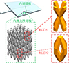 |
图1 空气舵结构示意图 |
本研究中空气舵点阵结构的基本单元为体心立方(body-center cubic, BBC)[22]几何构型,在宏观尺度上该点阵结构在空间上具有周期性重复特征,即沿3个主轴方向周期性重复变化。基于该周期性重复特征,可以提取点阵结构的重复性单元(repeated unit cell, RUC)[23],用于开展多尺度模拟分析。所得的RUC长4.0 mm、宽4.0 mm、高8.0 mm,且点阵杆件截面为1.0 mm×1.0 mm的矩形。由此可得点阵结构的空隙率为0.802,即相对密度为0.198。
理论上来说,采用合适的周期长度在结构的任一位置截取一RUC都能得到结构的全部信息,例如图 1所示的RUC#1或者RUC#2,沿3个主轴方向阵列后都可以得到与原始点阵序列相同的结构。但为了降低多尺度模拟分析的难度,截取RUC时应使得其边界面尽可能简单。图 1中RUC#1具有16个边界面,而RUC#2仅有6个边界面,因此本文选择边界面更少的RUC#2开展后续的多尺度模拟分析工作。
1.2 增材制造
本研究中的空气舵试验模型采用增材制造整体成型,原材料为GH3625粉末,工艺方法为选区激光熔化(selective laser melting, SLM)。所制备的空气舵试验模型实物照片和内部点阵结构CT检测结果如图 2所示。CT检测结果表明,空气舵试验模型的内部点阵结构完整,无初始缺陷。
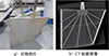 |
图2 增材制造的空气舵 |
2 点阵结构多尺度模拟
2.1 周期性边界条件
为RUC施加正确的周期性边界条件[24]是保证点阵结构多尺度模拟结果正确的必要条件,而施加周期性边界条件的前提是为RUC划分周期性网格,即要求RUC相对边界面上的网格节点一一对应。图 3为本文RUC的周期性网格划分结果。
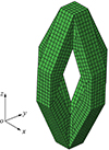 |
图3 RUC的周期性网格 |
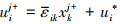
点阵结构具有周期性重复特征, (1)式给出了其周期性位移场的表达式。其中 表示RUC的平均应变, xk表示RUC内任意点的坐标, ui*为周期性位移修正量。
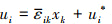 (1)
(1)
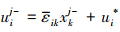
根据(1)式可以得到RUC相对边界面上的位移场满足(2)~(3)式, 其中上标“j+”, “j-”分别表示沿j轴(j=x, y, z)的正方向和负方向。
 (2)
(2)
 (3)
(3)
在RUC相对的边界面上ui*是相同的, 因此由(2)~(3)式相减可得(4)式。其中, Δxkj为RUC沿j轴方向的长度尺寸。
 (4)
(4)
为了进一步说明周期性边界条件是如何施加的, 以图 4所示的长方体RUC为例, 其顶点分别用A~H表示, 边分别用Ⅰ~Ⅻ表示, 面用各顶点组合表示。Wx, Wy, Wz分别表示该RUC沿x, y, z轴方向的长度尺寸。以顶点A为固定基点, 则可得到其周期性边界条件的约束方程如表 1所示。
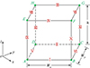 |
图4 RUC的几何示意图 |
周期性边界条件的约束方程
2.2 细观力学响应
采用图 3所示的RUC周期性网格模型开展点阵结构的多尺度模拟仿真, 分别沿x, y, z方向施加0.001的正应变, 并沿xy, xz, yz方向施加0.001的切应变, 计算所得的RUC内细观应力分布结果如图 5所示。
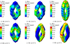 |
图5 RUC的细观应力分布 |
从图 5可以看出, 拉伸状态下: 当RUC受沿x方向的拉伸作用时, 主要由x方向上的连接杆件结构承载; 当RUC受沿y方向的拉伸作用时, 主要由y方向上的连接杆件结构承载; 当RUC受沿z方向的拉伸作用时, 由x与y方向上的连接杆件结构共同承载。剪切状态下: 当RUC受沿xy方向的剪切作用时, 由x与y方向上的连接杆件结构共同承载; 当RUC受沿xz方向的剪切作用时, 主要由x方向上的连接杆件结构承载; 当RUC受沿yz方向的剪切作用时, 主要由y方向上的连接杆件结构承载。
2.3 宏观等效力学性能参数
根据2.2节的多尺度模拟结果, 可采用体积平均法[13]计算该RUC的宏观等效材料参数, 即首先计算RUC在各种载荷状态下的宏观等效应力/应变, 然后反推出RUC的等效刚度矩阵, 最后从等效刚度矩阵计算得到该单胞的宏观等效材料常数, 结果如表 2所示。
RUC的宏观等效材料参数
从表 2中可看出, 本文研究的体心立方点阵结构在宏观上表现为正交各向异性[25]。
3 空气舵振动特性仿真
3.1 有限元模型
本研究的空气舵试验模型由增材制造整体加工,蒙皮、筋板与点阵结构一体成型。在商业有限元软件ABAQUS中建立的有限元模型如图 6所示。模型分为两部分:①实心蒙皮与实心筋板结构,其材料参数与GH3625材料一致,为各向同性材料;②多孔点阵结构,其材料参数采用第2节方法计算所得的宏观等效力学性能参数,为正交各向异性材料。两部分接触面之间不允许滑移,用关键字“*Tie”进行绑定约束。有限元模型采用四面体单元进行网格划分,共包含57 508个C3D10单元。有限元模型的边界条件与试验一致,即将舵轴完全固定。
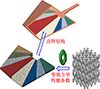 |
图6 空气舵有限元模型剖视图 |
3.2 仿真结果
采用3.1节建立的有限元模型,模拟得到该空气舵试验模型的前3阶模态振型,如图 7所示,固有频率依次为86.365, 187.75, 498.19 Hz。
 |
图7 空气舵前3阶模态振型仿真结果 |
4 试验验证
4.1 测试方法
振动特性测试过程试验照片如图 8所示,采用舵轴抱件将空气舵的旋转轴完全固定,并安装在支撑立面上。测试方式为固定激励点并在所有测点布置传感器,即空气舵下方采用激振器附带顶杆进行激励,上表面粘贴有7个IEPE型加速度传感器,用于采集振动信号数据,传感器的详细位置分布见图 9。激励扫频方式为50~600 Hz对数正弦扫频,单次扫描时间为12 s,扫描10次,共120 s。
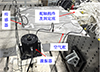 |
图8 空气舵振动特性测试过程 |
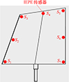 |
图9 传感器位置示意图 |
4.2 测试结果与分析
1) 固有频率
根据测试数据,采用快速傅里叶变换方法(fast fourier transform, FFT)[26]得到空气舵的频谱,如图 10所示。从图 10中可以看出,空气舵的前3阶固有频率依次为84.375, 195.125, 501.25 Hz。对比仿真结果可得,多尺度模拟仿真所得固有频率相对误差不超过5.0%,最大相对误差为3.78%,出现在第2阶固有频率处。
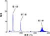 |
图10 空气舵前3阶固有频率测试结果 |
2) 振型
根据测试数据,采用特征系统实现算法(eigensystem realization algorithm, ERA)进行模态振型分析,得到空气舵的前3阶模态振型,如图 11所示。对比仿真结果可得,多尺度模拟仿真所得模态振型与试验测试结果一致。因此可以得出结论,本文发展的多尺度模拟方法可以较准确地计算得到空气舵的固有频率和模态振型。
 |
图11 空气舵前3阶模态振型测试结果 |
5 结论
1) 开展了含点阵结构空气舵的设计与增材制造,并完成了其振动特性的多尺度模拟方法和试验验证研究。
2) 基于细观有限元法获得了点阵结构的细观应力分布。结果表明,若点阵结构受载方向不同,内部应力在点阵杆件上的分布也将有很大差别。
3) 基于细观有限元法获得了宏观等效力学性能参数,结果表明体心立方点阵结构在宏观上表现为正交各向异性。
4) 多尺度模拟方法计算得到的空气舵固有频率和模态振型与试验测试结果基本一致,仿真所得前3阶固有频率相对误差不超过5.0%。
References
- SHI Guanghui, JIA Yibo, HAO Wenyu, et al. Optimal design of rudder structures based on data-driven method[J]. Chinese Journal of Theoretical and Applied Mechanics, 2023, 55(11): 2577–2587 (in Chinese) [Google Scholar]
- NIE Liang, LI Yu, LIU Yufei, et al. Effect of thermal-protection ring on flow and aeroheating of rudder shaft[J]. Physics of Gases, 2022, 7(4): 77–82 (in Chinese) [Google Scholar]
- BLAKEY-MILNER B, GRADL P, SNEDDEN G, et al. Metal additive manufacturing in aerospace: a review[J]. Materials & Design, 2021(12): 110008 [Google Scholar]
- YANG Weidong, LI Haonan, WANG Yuanyuan, et al. Review of non-uniform lattice structures for additive manufacturing[J]. Mechanical Science and Technology for Aerospace Engineering, 2024, 43(8): 1283–1296 (in Chinese) [Google Scholar]
- XU Yiyi, HU Jianxin, MIAO Xun, et al. Thermal protection technology and lattice structure application of scramjet engine[J]. Aerospace Technology, 2024(4): 24–42 (in Chinese) [Google Scholar]
- FAN H L, FANG D N, CHEN L M, et al. Manufacturing and testing of a CFRC sandwich cylinder with kagome cores[J]. Composites Science and Technology, 2009, 69(15/16): 2695–2700 [Google Scholar]
- XU Y, XU N, ZHANG W, et al. A multi-layer integrated thermal protection system with C/SiC composite and Ti alloy lattice sandwich[J]. Composite Structures, 2019, 230: 111507. [Article] [Google Scholar]
- CHEN J, HU L, AI H S. Bilayer lattice structure integrated with phase change material for innovative thermal protection system design[J]. Aerospace Science and Technology, 2023, 141(2): 108576 [Google Scholar]
- XIANG Yu, LIU Bin, ZHANG Shuzhe, et al. Lattice structure air rudder heat-fluid-structure interaction analysis[J]. Astronautical Systems Engineering Technology, 2018, 2(6): 52–58 (in Chinese) [Google Scholar]
- HUO Zekai, WANG Bo, ZHOU Yan, et al. Topology optimization of double-skin stiened sandwich structure for additivemanufacturing[J]. Chinese Journal of Computational Mechanics, 2023, 40(6): 861–871 (in Chinese) [Google Scholar]
- WU Z, LIU W, CHEN Y. Dual-scale optimization design and performance analysis of aircraft rudder structure[J]. Mechanics of Solids, 2024, 59(8): 4085–4099. [Article] [Google Scholar]
- WU Wenwang, XIA Re. Design of lightweight lattice meta-structures and approaches to manipulate their multi-functional mechanical properties[J]. Advances in Mechanics, 2022, 52(3): 673–718 (in Chinese) [Google Scholar]
- KONG Chunyuan, SUN Zhigang, GAO Xiguang, et al. Unit cell of 2.5 dimension C/SiC and its stiffness prediction[J]. Journal of Aerospace Power, 2011, 26(11): 2459–2467 (in Chinese) [Google Scholar]
- MACEDO R Q D, FERREIRA R T L, GUEDES J M, et al. Intraply failure criterion for unidirectional fiber reinforced compo-sites by means of asymptotic homogenization[J]. Composite Structures, 2016, 159: 335–349 [Google Scholar]
- ZHANG Chao, XU Xiwu, XU Xiaojing. Research progress in finite element analysis on macro-meso mechanical properties of 3D multi-directional braided composites[J]. Acta Materiae Compositae Sinica, 2015, 32(5): 1241–1251 (in Chinese) [Google Scholar]
- HU Dianyin, ZENG Yuqi, ZHANG Long, et al. Effective elastic constants prediction and modal test of 2D braided SiC/SiC cera-mic matrix composites[J]. Journal of Propulsion Technology, 2018(2): 1–8 (in Chinese) [Google Scholar]
- MASKERY I, AREMU A O, SIMONELLI M, et al. Mechanical properties of Ti-6Al-4V selectively laser melted parts with body-centred-cubic lattices of varying cell size[J]. Experimental Mechanics, 2015, 55(7): 1261–1272. [Article] [Google Scholar]
- LEARY M, MAZUR M, ELAMBASSERIL J, et al. Selective laser melting(SLM) of AlSi12Mg lattice structures[J]. Materials and Design, 2016, 98: 344–357. [Article] [Google Scholar]
- HUANG Kaixuan, DING Zhe, ZHANG Yan, et al. Topological optimization design method of layer-wise graded lattice structures with high load-bearing[J]. Chinese Journal of Theoretical and Applied Mechanics, 2023, 55(2): 433–444 (in Chinese) [Google Scholar]
- ZHANG Long, QIU Rongkai, CHENG Jun. Experimental investigation and multiscale simulation on the bending fatigue of 2D SiCf/SiC composites[J]. International Journal of Fatigue, 2021, 144: 106051. [Article] [Google Scholar]
- KANOUTÉ P, BOSO D P, CHABOCHE J L, et al. Multiscale methods for composites: a review[J]. Archives of Computational Methods in Engineering, 2009, 16: 31–75. [Article] [Google Scholar]
- GUO Chunhuan, WANG Lei, SHAO Shuaiqi, et al. Research progress on mechanical properties of metal lattice structure fabricated by laser powder bed fusion[J]. Materials Reports, 2025, 39(6): 24040109 (in Chinese) [Google Scholar]
- ZHANG Bo, WANG Guowei, SUN Mingyan, et al. Effect of cell and structural parameter on compression properties of SLMed gradient lattice structures[J]. Rare Metal Materials and Engineering, 2024, 53(4): 1021–1031 (in Chinese) [Google Scholar]
- ZHANG Chao, XU Xiwu, YAN Xue. General periodic boundary conditions and their application to micromechanical finite element analysis of textile composites[J]. Acta Aeronautica et Astronautica Sinica, 2013, 34(7): 1636–1645 (in Chinese) [Google Scholar]
- WU Hongfei, WANG Weirong, WANG Guowei, et al. Effect of anisotropy on mechanical properties of lattices structures manufactured by selective laser melting[J]. Rare Metal Materials and Engineering, 2022, 51(4): 1397–1405 (in Chinese) [Google Scholar]
- ZHAO Yinan, YAN Changfeng, MENG Jiadong, et al. Fault diagnosis of rolling bearings under variable speed conditions based on adaptive window rotation optimization short-time Fourier transform[J]. Journal of Vibration Engineering, 2024, 37(6): 1064–1076 (in Chinese) [Google Scholar]
All Tables
All Figures
|
图1 空气舵结构示意图 |
| In the text | |
|
图2 增材制造的空气舵 |
| In the text | |
|
图3 RUC的周期性网格 |
| In the text | |
|
图4 RUC的几何示意图 |
| In the text | |
|
图5 RUC的细观应力分布 |
| In the text | |
|
图6 空气舵有限元模型剖视图 |
| In the text | |
|
图7 空气舵前3阶模态振型仿真结果 |
| In the text | |
|
图8 空气舵振动特性测试过程 |
| In the text | |
|
图9 传感器位置示意图 |
| In the text | |
|
图10 空气舵前3阶固有频率测试结果 |
| In the text | |
|
图11 空气舵前3阶模态振型测试结果 |
| In the text | |
Current usage metrics show cumulative count of Article Views (full-text article views including HTML views, PDF and ePub downloads, according to the available data) and Abstracts Views on Vision4Press platform.
Data correspond to usage on the plateform after 2015. The current usage metrics is available 48-96 hours after online publication and is updated daily on week days.
Initial download of the metrics may take a while.