| Issue |
JNWPU
Volume 42, Number 6, December 2024
|
|
|---|---|---|
| Page(s) | 1119 - 1125 | |
| DOI | https://doi.org/10.1051/jnwpu/20244261119 | |
| Published online | 03 February 2025 | |
Novel static calculation approach for reciprocal structures assembled by Archimedes paving curved rods
阿基米德铺砌曲杆互承结构的静力计算方法
1
School of Civil Engineering and Architecture, Zhejiang University of Science and Technology, Hangzhou 310023, China
2
School of Management, Zhejiang University of Technology, Hangzhou 310023, China
3
Faculty of Social Science and Law, University of Bristol, Bristol BS8, UK
4
College of Civil Engineering and Architecture, Zhejiang University, Hangzhou 310058, China
Received:
13
October
2023
Abstract
In order to more efficiently solve the internal forces and deformations of the curved rod reciprocal structures transformed from the Archimedes paving, the reference point is defined on the curved rod element in this paper. On the basic of the static equilibrium relationship between the forces at the reciprocal articulated joints and the generalized nodal loads at the reference point, the static equilibrium equation of the curved rod reciprocal structure is established. By solving the equilibrium equation, the nodal forces of the curved rod reciprocal structure can be obtained. Furthermore, the internal forces and deformations of the reciprocal curved rod in the cylindrical coordinate system are derived by coordinate transformations. Finally, a quadrilateral curved rod reciprocal frame and a curved rod reciprocal structure transformed from the 63 type of Archimedes paving are studied respectively by proposed method and finite element method with ANSYS software. Results shows that the error rate of the nodal forces and nodal displacements between the numerical simulation and the theoretical calculation is less than 5%. The proposed method is not only reliable in static forces calculation, but also simplicity and efficiency in solution process.
摘要
为了更加高效地求解阿基米德铺砌曲杆互承结构的内力和变形, 在曲杆单元上定义基准点, 根据互承节点连接力和基准点广义节点荷载之间的平衡关系, 建立了曲杆互承结构静力平衡方程, 求解平衡方程, 即可得到曲杆互承结构的节点连接力; 通过坐标变换, 推导了互承曲杆在柱面坐标系下的内力和变形表达式。采用文中方法对四边形曲杆互承结构和阿基米德63型曲杆互承结构进行算例分析, 并与ANSYS软件有限元分析结果进行对比验证, 结果表明: 2种方法所得节点连接力和节点位移误差在5%以内, 文中方法不仅计算结果正确可靠, 而且计算过程更加简洁高效。
Key words: curved rod reciprocal structure / Archimedes paving / static calculation / cylindrical coordinate system / finite element analysis(FEA)
关键字 : 曲杆互承结构 / 阿基米德铺砌 / 静力计算 / 柱面坐标系 / 有限元分析(FEA)
© 2024 Journal of Northwestern Polytechnical University. All rights reserved.
 This is an Open Access article distributed under the terms of the Creative Commons Attribution License (https://creativecommons.org/licenses/by/4.0), which permits unrestricted use, distribution, and reproduction in any medium, provided the original work is properly cited.
近年来, 构型独特的互承结构成为学术界一个新的研究兴趣点[1–2]。目前, 这类结构主要应用于空间结构屋盖设计、临时建筑搭建等领域[3–4]。Baverel等[5–6]对互承结构的形状生成问题进行了初步研究, 提出了直接构型法。武岳等[7–9]优化了互承结构的构型方法, 提出了循环搭接法。Song等[10–11]设计了一整套可以快速实现互承构型的实用性工具。Asefi等[12]搭建了互承结构的设计框架, 编制了一套用于互承结构制造和维护的应用程序。
互承构型能否成为互承结构, 需要进行静动定特性判定。Parigi等[13–14]、夏永强等[15–16]以杆件位移为基本未知量建立位移协调方程, 提出了互承构型的静动定特性判定方法。研究表明, 基于11种阿基米德平面铺砌变换而来的互承结构为静定结构。Rizzuto等[17–19]借助数值模拟和模型试验对互承体系的结构性能进行了深入研究, 夏永强等[20]提出了静定直杆互承结构的内力计算方法。
在实际工程中, 互承结构必须满足建筑的整体造型要求。目前, 互承结构的基本单元大多数是由直杆构成, 为了满足杆件两两相互搭接的几何关系, 杆件规格种类经常过于繁多[21]。为此, Larsen等[22]提出了曲杆互承结构, 与直杆互承结构相比, 曲杆互承结构构型过程更加灵活性, 更容易实现目标曲面。然而, 曲杆的加入, 使得该类结构的力学特性分析变得复杂, 提出一套适用于曲杆互承结构的静力计算方法, 是当前亟待解决的问题。
本文在曲杆单元上定义基准点, 根据互承节点连接力和基准点广义节点荷载之间的平衡关系, 建立了曲杆互承结构静力平衡方程; 通过坐标变换, 推导了互承曲杆在柱面坐标系下的内力和变形表达式。提出了适用于阿基米德铺砌曲杆互承结构的静力计算方法。最后, 采用提出的方法对四边形曲杆互承结构和阿基米德63型曲杆互承结构进行计算分析, 并借助ANSYS有限元进行对比验证。
1 空间曲杆单元的平衡条件
如图 1所示, 曲线段为空间曲杆l的轴心线, ki, kj分别为曲杆的2个端点。点p为曲杆与其他杆件的互承搭接点, 图 1蓝色方框为搭接点p所在的曲杆横截面, 点p′为横截面与轴心线的交点。在整体坐标系O-XYZ下, 搭接点p处作用有节点连接力向量fp={fpX, fpY, fpZ}T; 以点kj为曲杆基准点r, 在基准点r上, 作用有广义节点荷载向量Pr={PrX, PrY, PrZ, MPrX, MPrY, MPrZ}T。曲杆应在节点连接力fp和基准点广义节点荷载Pr共同作用下, 保持平衡。假定曲杆绝对刚性, 根据静力平衡关系有
 (1)
(1)
式中
 (2)
(2)
矩阵Apr为曲杆单元广义平衡矩阵, 其含义是: 当曲杆上仅p点处作用单位力I时, 在曲杆广义基准点r上与之平衡的基准点广义节点荷载为- Apr I。
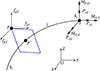 |
图1 空间曲杆单元 |
2 曲杆互承结构的平衡方程
如图 2所示,3根曲杆组成三角形曲杆互承单元。图 2中ln(n=1, 2, 3)表示第n号杆件;pn表示曲杆ln上的内部互承节点;rn表示曲杆ln的基准点;Prn为作用在曲杆基准点rn上的节点荷载;cn为曲杆ln的支座节点;Rn为支座cn的支座反力。令m=n+1,且n=3时,m=1。以作用于ln上的节点连接力fpn为正,则杆件ln上作用有2个节点连接力fpn和- fpn。对曲杆ln,根据力的平衡关系,有
 (3)
(3)
对于整个三角形曲杆互承体系, 体系的静力平衡方程可以表示为
 (4)
(4)
对于由Nl根曲件, Np个内部互承节点和Nc个支座约束组成的任一曲杆互承结构, 共3Np+Nc个未知数组成节点连接力向量f, 共6Nl个数组成基准点荷载向量P, 因此, 可以得到曲杆互承结构的静力平衡方程为
 (5)
(5)
矩阵A为曲杆互承体系的平衡矩阵, 它反映了曲杆所受到的基准点广义节点荷载P和互承搭接点处节点连接力(支座反力) f之间的关系。对于没有多余约束的静定互承结构, 平衡矩阵A为可逆矩阵, 即rank(A)=3Np+Nc=6Nl, 因此, 结构的节点连接力(支座反力) f可以通过直接求解(6)式获得。
 (6)
(6)
对于作用有一般荷载的曲杆互承结构, 基准点广义节点荷载P无法直接获得, 需要先对单根曲杆进行分析, 利用结构力学中的叠加原理[23], 在保证曲杆产生相同节点约束力的基础上, 将一般荷载等效成基准点广义节点荷载。
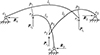 |
图2 三角形曲杆互承单元 |
3 曲杆单元的内力和变形
如图 1所示, 先将曲杆单元l所受到的节点连接力fp从点p等效到轴心线上(点p′)。根据图 3, 点p′上的等效节点连接力fp′为
 (7)
(7)
求得的节点连接力和支座反力都是在整体坐标系O-XYZ下描述的, 为了求解杆件单元的内力和变形, 需要将整体坐标系下的力转换到杆件截面主惯性轴的方向。
如图 4所示, 连接曲杆端点ki, kj, 过点p′做kikj的垂线, 以垂足为坐标原点 O, kikj所在的直线为 X轴, 点p′和原点O的连线为Z轴, Y轴按右手法则确定, 建立单元局部坐标系 O-XYZ。单元局部坐标系O-XYZ和整体坐标系O-XYZ下的节点连接力的转换关系为 fp′= Tfp′, 其中
 (8)
(8)
 (9)
(9)
式中,υXX, υXY, υXZ为单元局部坐标系O-XYZ的X轴分别与整体坐标系O-XYZ的X, Y, Z坐标轴的方向余弦, 其余同。
对于曲杆单元, 通常采用柱面坐标系描述其内力和变形。图 5是基于点p′的曲杆单元柱面坐标Oρ-ρθρZρ, 坐标系圆柱中轴线过点p′处的曲率圆圆心Oρ, 当曲杆轴心线是定曲率圆弧时, 曲杆上各点的柱面坐标系是相同的。在柱面坐标系Oρ-ρθρZρ下, 曲杆上任意一点的坐标都可用3个坐标参数ρ, θρ, Zρ描述。容易看出, 单元局部坐标系O-XYZ的Y轴平行于Zρ轴, 因此, 将Y轴方向的节点连接力 fp′Y和Mp′Y转移到柱面坐标系Oρ-ρθρZρ中, 可以表示为
 (10)
(10)
 (11)
(11)
图 6是柱面坐标系的Oρ-ρθρ面, 沿单元局部坐标系O-XYZ的X轴和Z轴的节点连接力可以分别分解成柱面坐标系下的环向力和径向力。
 (12)
(12)
 (13)
(13)
 (14)
(14)
 (15)
(15)
经过上述计算, 点p′处的节点连接力从整体坐标系O-XYZ中的fp′转换成曲杆单元柱面坐标系Oρ-ρθρZρ中的节点连接力fp′c。实际工程中, 为了施工方便, 一般令曲杆的一条主惯性轴垂直于曲杆所在的弯曲平面。如图 7所示, y轴与向量n平行, 图中: y, z分别为曲杆截面的2条主惯性轴, n为曲杆弯曲平面的法向量。可以看出, 此时, 单元柱面坐标系Oρ-ρθρZρ下的节点连接力fp′c的方向与杆件主惯性轴的方向是一致的。
同样地, 对于整体坐标系O-XYZ下的基准点广义节点荷载Pr, 也可以用曲杆单元柱面坐标系Oρ-ρθρZρ表示。至此, 可以求出在节点连接力和基准点广义节点荷载共同作用下, 柱面坐标系下曲杆l上任一点的内力。进一步, 借助文献[24]推导的曲梁刚度矩阵, 可以求出曲杆的变形。
上述推导过程都是在单曲率曲杆模型基础上完成的, 对于多曲率曲杆, 需要采用多套柱面坐标系统进行描述, 提出的方法仍然适用。
和直杆互承结构相比, 曲杆互承结构内力计算需要灵活运用笛卡尔直角坐标系和柱面坐标系2套坐标系统的转换, 杆件单元的平衡关系、节点位移和节点力以及刚度矩阵的描述都与直杆互承结构有很大区别, 理论推导过程更为复杂。
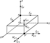 |
图3 曲杆单元的节点连接力 |
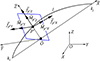 |
图4 单元局部坐标系O-XYZ |
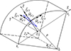 |
图5 基于点p′的曲杆单元柱面坐标系Oρ-ρθρZρ |
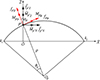 |
图6 曲杆单元柱面坐标系的Oρ-ρθρ面 |
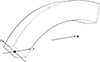 |
图7 空间曲杆单元的主惯性轴和方向向量 |
4 算例分析及有限元验证
4.1 四边形曲杆互承结构静力计算
图 8是一个四边形曲杆互承结构, 4根杆件均为直径D=400 mm、曲率半径2.3 m的定曲率等截面圆杆, 杆件2个端点的直线距离为3.2 m, 互承结合率为64%, 每根曲杆弯曲平面的法向量n均平行于整体坐标系XOY平面。曲杆的弹性模量取2.06×10¹¹ N/m2, 密度取7.9×10³ kg/m3, 泊松比取0.3。4根杆件的自由端均与基础铰接, 在4个互承搭接点处沿Z负向施加集中荷载10 N。图中: 编号①~④表示互承搭接点, 位于杆件截面边缘; 编号⑤~⑧表示支座点, 位于所在杆件的轴心线上。可以看出, 该构型杆件数Nl=4, 互承搭接点数Np=4, 支座位移约束数Nc=12。用本文提出的方法, 集成得到体系的平衡矩阵A, 奇异值分解得到平衡矩阵的秩为rank(A)=24, 体系为静定结构, 可以根据(6)式求得节点连接力, 结果见表 1。
为了检验提出方法计算结果的正确性, 采用ANSYS软件进行有限元分析。曲杆采用Beam189单元模拟, 不考虑几何非线性。在互承节点位置建立短刚臂, 用来模拟实际搭接情况。刚臂用Beam189单元模拟, 弹性模量取为2×1050 N/m2, 密度和泊松比均取为0。结构的有限元模型如图 9所示。提取ANSYS计算所得的节点连接力, 并与提出方法计算结果进行对比, 结果见表 1, 表中η=max(ηX, ηY, ηZ), 其中:  , i=X, Y, Z, fi为提出方法计算的节点连接力; f′i为ANSYS计算的节点连接力。由表 1可知: 2种方法计算所得结果基本一致, 偏差最大的点为①号节点, η=3.9%, 小于5%的工程容许误差。
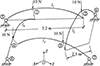 |
图8 四边形曲杆互承结构几何尺寸 |
四边形曲杆互承结构的节点连接力
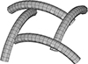 |
图9 四边形曲杆互承结构有限元模型 |
4.2 阿基米德63型互承结构静力计算
图 10是阿基米德63型球面曲杆互承结构, 球面跨度为4 m。每根杆件为直径100 mm、曲率半径1.2 m的等截面圆杆, 杆件2个端点的直线距离为1.4 m, 互承结合率为33%, 每根曲杆弯曲平面的法向量n均平行于整体坐标系XOY平面。曲杆自由端与基础铰接, 在图示3个互承搭接点上沿Z负向分别施加集中荷载20 N。容易看出, 对该互承结构, 同样满足rank(A)=6Nl=3Np+Nc=72, 为静定结构。
用(6)式计算该构型的节点连接力, 并借助ANSYS有限元进行对比验证, 杆件材料特性、ANSYS单元选取等同4.1节中的算例。2种方法计算所得的节点连接力和节点位移数据对比如图 11所示, 图中:  , i=X, Y, Z, di为提出方法计算的节点位移; d′i为ANSYS计算的节点位移。
分析图 11中数据, 可以看出2种方法所得结果误差率小于5%, 满足工程容许误差。但数据并不完全吻合, 原因有以下2个方面:
1) ANSYS建模时通过引入短刚臂来模拟互承搭接关系, 尽管刚臂的弹性模量取值很大, 仍非绝对意义上的刚性杆, 与真实情况存在偏差;
2) 本文提出的方法将曲杆视为刚性杆建立平衡关系, 不考虑杆件的变形, 而有限元分析时, 除了平衡关系, 还考虑了变形协调关系。
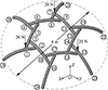 |
图10 阿基米德63型曲杆互承结构几何尺寸 |
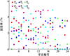 |
图11 阿基米德63型曲杆互承结构节点连接力和节点位移数据对比 |
5 结论
在曲杆单元上定义基准点, 基于互承节点连接力和基准点广义节点荷载之间的平衡关系, 建立曲杆互承结构静力平衡方程。对于11种阿基米德铺砌变换而来的静定曲杆互承结构, 节点连接力可通过求解平衡方程直接获得。进一步, 通过坐标变换, 可以得到互承曲杆在柱面坐标系下的内力和变形。
利用提出的方法分别对四边形曲杆互承结构和阿基米德63型曲杆互承结构进行计算分析, 并借助ANSYS有限元软件进行对比验证, 结果表明: 2种方法所得节点连接力和节点位移误差在5%以内, 验证了提出方法的正确性。
使用传统有限单元法分析曲杆互承结构时, 为了描述曲杆两两相互搭接的几何关系, 需要额外增加短刚臂, 对于拓扑形式复杂的大型曲杆互承结构, 不仅会带来巨大的建模工作量, 还有可能因刚臂刚度取值不当, 导致数值计算难以收敛。本文提供的方法在已知互承构型的情况下, 曲杆的几何特性已经确定, 不需要专门定位搭接点, 在实际计算时, 能更加方便快捷地计算出互承搭接点的节点连接力, 进而获得每一根曲杆的内力和变形。
References
- BEATRIZ D R C, JOAQUÍG E, ALFONSO G S. Architectural systemic approach: the serpentine gallery 2005, a reciprocal frame case study[J]. Buildings, 2022, 12(7): 1–34 [Google Scholar]
- MACIEJ P. Static analysis of structural grillages made of steel reciprocal beams[J]. Engineering Structures, 2023, 291: 1–11. [Article] [Google Scholar]
- PEREZ V J, MUNOZ V M, SUAREZ R F, et al. Deployable cylindrical vaults with reciprocal linkages for emergency buildings[J]. Structures, 2021, 33: 4461–4474. [Article] [CrossRef] [Google Scholar]
- SU Y, ZHANG J Y, OHSAKI M, et al. Topology optimization and shape design method for large-span tensegrity structures with reciprocal struts[J]. International Journal of Solids and Structures, 2020, 206: 9–22. [Article] [CrossRef] [Google Scholar]
- BAVEREL O. Nexorades: a family of interwoven space structures[D]. Surrey: University of Surrey, 2000 [Google Scholar]
- DOUTHE C, BAVEREL O. Design of nexorades or reciprocal frame systems with the dynamic relaxation method[J]. Computers & Structures, 2009, 87(21/22): 1296–1307. [Article] [CrossRef] [Google Scholar]
- WU Yue, SU Yan, QIAO Gang. A form-finding method for reciprocal spatial grid structure[J]. Journal of Building Structure, 2018, 39(7): 11–17 (in Chinese) [Google Scholar]
- SU Y, OHSAKI M, WU Y, et al. A numerical method for form finding and shape optimization of reciprocal structures[J]. Engineering Structures, 2019, 198: 1–12. [Article] [Google Scholar]
- SU Y, WU Y, QIAO G, et al. Self-adaptive form generation method for reciprocal grid structures[J]. Computer-Aided Civil and Infrastructure Engineering, 2019, 34(5): 444–454. [Article] [CrossRef] [Google Scholar]
- SONG P, FU C W, GOSWAMI P, et al. Reciprocal frame structures made easy[J]. ACM Trans on Graphics, 2013, 32(4): 94–95. [Article] [CrossRef] [Google Scholar]
- SONG P, FU C W, GOSWAMI P, et al. An interactive computational design tool for large reciprocal frame structures[J]. Nexus Network Journal, 2014, 16(1): 109–118. [Article] [CrossRef] [Google Scholar]
- ASEFI M, BAHREMANDI-TOLOU M. Design challenges of reciprocal frame structures in architecture[J]. Journal of Building Engineering, 2019, 26: 1–16. [Article] [Google Scholar]
- PARIGI D, SASSONE M, KIRKEGAARD P H, et al. Static and kinematic formulation of planar reciprocal assemblies[J]. Nexus Network Journal, 2014, 16(1): 37–59. [Article] [CrossRef] [Google Scholar]
- SASSONE M, PARIGI D. On deployable reciprocal frames from the mathematical description to the architectural applications[C]//Proceedings of Structures and Architecture, London, 2010: 233–234 [Google Scholar]
- XIA Yongqiang, XIAO Nan, QIAN Xiaoqian. Investigation on determination method of static and kinematic determinacy by matrix analysis for reciprocal configurations[J]. Journal of Building Structures, 2020, 41(3): 140–149 (in Chinese) [Google Scholar]
- XIA Y Q, XIAO N, CHEN H P, et al. Determination of static and kinematic determinacy of pin-jointed assemblies using rigid-body displacements as primary unknown variables[J]. Engineering Structures, 2019, 181: 643–652. [Article] [CrossRef] [Google Scholar]
- RIZZUTO J P. Dodecahedric mutually supported element space structure-numerical modeling[J]. Journal of the International Association for Shell and Spatial Structues, 2008, 49(1): 3–18 [Google Scholar]
- RIZZUTO J P. Experimental investigation of reciprocally supported element(RSE) lattice honeycomb domes structural behaviour[J]. Engineering Structures, 2018, 166: 496–510. [Article] [CrossRef] [Google Scholar]
- RIZZUTO J P, HULSE R. Dodecahedric mutually supported element space structure: experimental investigation[J]. International Journal of Space Structures, 2007, 22(2): 107–121. [Article] [CrossRef] [Google Scholar]
- XIA Yongqiang, XIAO Nan, QIAN Xiaoqian. Novel approach to calculation of internal forces for the reciprocal frames with hinged girders[J]. Journal of Huazhong University of Science and Technology, 2019, 47(3): 115–120 (in Chinese) [Google Scholar]
- XU Xiaoyan, XIAO Nan, FAN Binghe. Feasibility determination of common cylindrical grids converting to reciprocal configurations[J]. Journal of Zhejiang University, 2018, 52(8): 1583–1595 (in Chinese) [Google Scholar]
- LARSEN O P, BRANCART S, TEMMERMAN N D, et al. Bending-active reciprocal structures based on equilateral polyhedral geometries[C]//Proceedings of the IASS Annual Symposium, Hamburg, 2017: 1–11 [Google Scholar]
- LONG Yuqiu, BAO Shihua, YUAN Si. Structural mechanics Ⅰ, basic tutorial[M]. Beijing: Higher Education Press, 2012 (in Chinese) [Google Scholar]
- CAI Shihong, WU Yunchuan, FANG Gaoni. Element stiffness matrix and nodal load matrix of circular beam[J]. Journal of Anhui Institute of Architecture & Industry, 2003, 11(4): 17–22 (in Chinese) [Google Scholar]
All Tables
All Figures
|
图1 空间曲杆单元 |
| In the text | |
|
图2 三角形曲杆互承单元 |
| In the text | |
|
图3 曲杆单元的节点连接力 |
| In the text | |
|
图4 单元局部坐标系O-XYZ |
| In the text | |
|
图5 基于点p′的曲杆单元柱面坐标系Oρ-ρθρZρ |
| In the text | |
|
图6 曲杆单元柱面坐标系的Oρ-ρθρ面 |
| In the text | |
|
图7 空间曲杆单元的主惯性轴和方向向量 |
| In the text | |
|
图8 四边形曲杆互承结构几何尺寸 |
| In the text | |
|
图9 四边形曲杆互承结构有限元模型 |
| In the text | |
|
图10 阿基米德63型曲杆互承结构几何尺寸 |
| In the text | |
|
图11 阿基米德63型曲杆互承结构节点连接力和节点位移数据对比 |
| In the text | |
Current usage metrics show cumulative count of Article Views (full-text article views including HTML views, PDF and ePub downloads, according to the available data) and Abstracts Views on Vision4Press platform.
Data correspond to usage on the plateform after 2015. The current usage metrics is available 48-96 hours after online publication and is updated daily on week days.
Initial download of the metrics may take a while.