| Issue |
JNWPU
Volume 43, Number 6, December 2025
|
|
|---|---|---|
| Page(s) | 1192 - 1200 | |
| DOI | https://doi.org/10.1051/jnwpu/20254361192 | |
| Published online | 02 February 2026 | |
Analysis of meshing characteristics of incomplete gear pair in planetary roller screw mechanism
行星滚柱丝杠不完整齿轮副啮合特性分析
School of Mechanical Engineering, Northwestern Polytechnical University, Xi'an 710072, China
Received:
12
March
2025
Abstract
Based on the roller thread equation, the spur tooth profile equation, and coordinate transformation relationships, the surface equations of the incomplete gear pairs in the planetary roller screw mechanism were established. Combining the gear meshing principle with the surface equations of incomplete gear pairs, a model for calculating the contact point positions and contact line lengths of incomplete gear pairs was proposed. A finite element model for incomplete gear pair was introduced to validate the correctness of the present model. The influence of the initial angle and width of the spur gear on the meshing characteristics of incomplete gear pairs was analyzed. The results show that under the same meshing radius, the maximum and minimum contact line lengths on each spur tooth structure are not affected by the initial angles of the roller's spur tooth profile and the roller's spur thread. The analysis shows that when the tooth width of the incomplete gear pair is an integer multiple of the roller thread lead, under the same meshing radius, the contact line lengths on any spur tooth structure are identical.
摘要
根据滚柱螺纹方程、直齿齿廓方程与坐标变换关系, 建立行星滚柱丝杠中不完整齿轮副曲面方程。基于齿轮啮合原理与不完整齿轮副曲面方程, 求解不完整齿轮副的接触点位置与接触线长度。建立不完整齿轮副的有限元模型, 验证了不完整齿轮副啮合模型的正确性。分析行星滚柱丝杠不完整齿轮副的啮合特性, 结果表明: 不完整齿轮副在同一啮合半径下, 各直齿结构上接触线长度的最大值与最小值不受滚柱直齿齿廓起始角度与滚柱直齿螺纹起始角度的影响; 当不完整齿轮副齿宽为滚柱螺纹导程的整数倍时, 同一啮合半径下, 任一直齿结构上的接触线长度均相同。
Key words: planetary roller screw mechanism (PRSM) / incomplete gear pair / meshing characteristics / contact line length
关键字 : 行星滚柱丝杠 / 不完整齿轮副 / 啮合特性 / 接触线长度
© 2025 Journal of Northwestern Polytechnical University. All rights reserved.
 This is an Open Access article distributed under the terms of the Creative Commons Attribution License (https://creativecommons.org/licenses/by/4.0), which permits unrestricted use, distribution, and reproduction in any medium, provided the original work is properly cited.
行星滚柱丝杠(planetary roller screw mechanism, PRSM)是一种通过螺纹啮合将旋转运动转换为直线运动的机械传动装置。与滚珠丝杠机构相比, PRSM的接触方式更为均匀, 相同体积内的接触点更多, 因此具有承载能力大、效率高、寿命长等特点, 目前已被广泛应用于数控机床、工业机器人、航空航天等领域。根据主动件的不同, 可以将PRSM分为标准式PRSM和反向式PRSM, 标准式PRSM以丝杠的旋转运动作为输入, 以螺母的直线运动作为输出; 反向式PRSM以长螺母的旋转运动作为输入, 以中空丝杠的直线运动作为输出。
啮合特性研究是进行PRSM传动精度与动态响应分析的基础, 亦是其齿形优化设计、摩擦磨损调控和润滑寿命预估等的前提。在PRSM螺纹副啮合特性研究中, 国内外针对啮合接触位置与轴向间隙的计算模型主要分为数值啮合和解析啮合2类。数值模型方面, Blinov、Ryakhovskiy及Fedosovsky等[1–3]通过离散化方法构建了典型解决方案: 在螺纹重叠区域建立高密度网格系统, 将滚柱与丝杠/螺母的曲面啮合问题转化为网格节点处的空间坐标差值计算, 实现了复杂接触问题的数值表征。解析模型研究则基于微分几何原理展开, 付晓军与Jones等[4–5]通过建立曲面相切接触条件的数学模型, 推导出行星滚柱丝杠副的啮合方程解析式。该模型通过参数化方法实现轴向间隙的精确计算, 为系统设计提供了理论闭环解。
受PRSM的特殊传动结构与加工工艺限制, 滚柱两端齿轮因螺纹切割导致其齿轮结构不完整, 造成滚柱两端齿轮与内齿圈或丝杠之间轴向非连续啮合, 形成不完整齿轮副。不完整齿轮副的作用是约束滚柱的轴向和旋转自由度, 实现运动同步、载荷均布及传动精度控制, 从而增强PRSM的系统稳定性和可靠性。针对PRSM不完整齿轮副的研究, 国内外学者主要围绕参数与工艺优化、动态特性分析等方向开展相关研究。
在参数与工艺优化领域, 韦振兴等[6]通过引入乘除法与模拟退火算法的混合策略, 实现了参数全局优化。Zavyalov等[7]开发了基于轮廓仪测量与数学建模的PRSM不完整齿轮副标准化参数体系, 在保证质量控制的同时, 将其螺纹几何参数的检测效率提升45%。在动态特性研究领域, 马尚君等[8]揭示了滚柱螺纹节圆与滚柱直齿节圆偏移对PRSM运动参数的动态影响; Jones等[9]阐明了节圆不匹配导致的滚柱轴向迁移现象及其对系统导程的边界约束; Xing等[10]基于节圆误差模型分析了齿轮副啮合滑动速度的方向和大小变化规律。Fu等[11–13]则在动态建模方向取得突破, 通过六自由度非线性模型量化了接触力、压力角、摩擦-润滑耦合的非线性效应, 并构建含误差的啮合运动学框架, 为载荷分布与误差传递研究提供理论工具。许千斤等[14]聚焦齿轮副啮合激励与惯性力的耦合作用, 提出其对螺纹副动载荷分布的调控机制; 马腾龙等[15]则深入研究螺纹副-齿轮副同步啮合机制, 解析转速、负载对接触载荷波动特性的影响。
现有国内外研究均表明PRSM中的齿轮副啮合状态会对其运动及动态承载特性产生重要影响, 但缺乏考虑螺纹与直齿结构耦合的PRSM不完整齿轮副啮合模型, 无法高效准确地对其啮合特性进行分析。因此, 本文通过研究标准式PRSM与反向式PRSM中的不完整齿轮副, 给出不完整齿轮副的曲面方程, 分析滚柱直齿螺纹起始角度、齿廓起始角度与不完整齿轮副齿宽对接触线长度的影响, 为PRSM螺纹副-齿轮副耦合承载及振动分析提供理论基础。
1 PRSM不完整齿轮副结构
1.1 内啮合与外啮合不完整齿轮副
标准式PRSM中, 滚柱端部的直齿结构需同时与丝杠螺纹和安装在螺母端部的内齿圈相匹配, 如图 1所示, 滚柱直齿和内齿圈共同组成一对内啮合不完整齿轮副。 和
和 分别为内啮合固定坐标系与滚柱坐标系, Z1轴和zR1轴均与滚柱轴线重合, 且
 随滚柱旋转。
 为内齿圈坐标系, zRg1轴与内齿圈轴线重合, 且原点oRg1和oR1的连线与xRg1轴相重合。
反向式PRSM中, 滚柱端部的直齿结构需同时与螺母螺纹和安装在丝杠端部的外齿圈相匹配, 如图 2所示, 滚柱直齿和外齿圈共同组成一对外啮合不完整齿轮副。采用与标准式PRSM类似的方式, 在图 2中建立外啮合固定坐标系 、滚柱坐标系
 和外齿圈坐标系
 。
。

 (1)
(1)
 (2)
(2)
式中: φi为滚柱坐标系 相对于固定坐标系
 在Zi轴周向的旋转角度。
内齿圈坐标系 向内啮合固定坐标系
 的坐标变换为:
 (3)
(3)
 (4)
(4)
式中: ZR1和ZRg1分别为滚柱直齿与内齿圈的齿数; aR1为内啮合不完整齿轮副的中心距。
外齿圈坐标系 向外啮合固定坐标系
 的坐标变换为:
 (5)
(5)
 (6)
(6)
式中:ZWt2为外齿圈的齿数; aR2为内啮合不完整齿轮副的中心距。
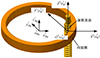 |
图1 内啮合不完整齿轮副坐标系 |
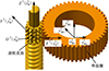 |
图2 外啮合不完整齿轮副坐标系 |
1.2 滚柱不完整直齿结构
如图 3所示, 滚柱直齿同时具有螺纹和直齿结构。因为滚柱直齿结构仅会出现在如图 3蓝色虚线所围的螺纹结构上, 所以区别于传统直齿轮, 滚柱直齿沿着zRi轴方向结构并不完整, 是由多个既有齿轮特征又有螺纹特征的齿牙所构成。
假设图 3所示滚柱直齿的齿数为ZiR, 定义沿着轴线方向, 被图 3红色虚线椭圆所圈入结构为1个滚柱直齿结构, 则滚柱直齿jiR为沿顺时针方向靠近xiR正半轴的第jiR个直齿结构, 且jiR=1, 2, …, ZiR。如图 3所示, 滚柱直齿jiR共由 段非连续齿牙所构成, 则滚柱齿牙jiR×q为直齿结构jiR上沿ziR轴方向靠近
 平面的第q个齿牙, 且
 。
。
滚柱不完整直齿中, 螺纹结构与齿轮结构的相位关系定义如图 4所示。图 4中, riR是直齿结构的分度圆半径; 曲线ΓiR为直齿结构1靠近xiR正半轴的一侧齿面在 平面上的投影, 并定义φiR0为曲线ΓiR在零件坐标系
 中的起始角度,
  为滚柱直齿的齿宽;
  为滚柱直齿螺纹结构截面坐标系, ri为滚柱螺纹的名义半径; λi为滚柱螺纹的螺旋升角; 曲线ΓiT为半径ri、螺旋升角λi的圆柱螺旋线, 曲线ΓiTe为曲线ΓiT向ziR负半轴延伸的圆柱螺旋线; 截面坐标系的原点ois在曲线ΓiT或ΓiTe上, wis轴与ziR轴平行, 平面
 通过ziR轴; θi0为曲线ΓiT在坐标系
 中的起始角度; θi为点ois与曲线ΓiT起始点在平面
 上关于点oiR的夹角。
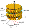 |
图3 滚柱直齿结构组成 |
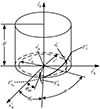 |
图4 滚柱直齿零件坐标系 |
2 不完整齿轮副曲面方程
根据螺旋曲面的参数表示方法[16], 由坐标变换关系得滚柱直齿中螺旋结构的螺旋曲面方程为
 (7)
(7)
式中: 上标i=1, 2分别代表内啮合和外啮合; ui和θi代表滚柱直齿中螺纹结构的螺纹曲面方程在其零件坐标系中的曲面坐标, 其中 取1或-1代表滚柱螺旋结构的上或下螺旋曲面。由(7)式与渐开线齿面角度关系得滚柱直齿、内齿圈和外齿圈在各自坐标系中的统一直齿齿廓方程为
 (8)
(8)
 (9)
(9)
式中:下标k取R, Rg和Wt分别代表滚柱直齿、内齿圈与外齿圈; jki为直齿齿廓中第jki个直齿结构, jki∈(0, 1, …, Zki); ξik2取1或-1代表前或后渐开线齿面; rki为渐开线上一点的向径; θki为渐开线上该点与基圆法线之间的展角; αki为渐开线在该点的压力角; ribk为基圆半径; φki为齿厚关于圆心的夹角, 其值为 为两侧渐开线在分度圆上点与基圆法线关于圆心的夹角; αki为齿廓渐开线在该点的压力角。αki的取值范围为
 (10)
(10)
式中:  是直齿齿廓在零件坐标系中的起始角度, 其中
 和
和 分别为当φi=0时, 内齿圈和外齿圈与滚柱直齿相啮合直齿齿廓在各自零件坐标系中的初始角度。
 和
和 的值分别为
的值分别为
 (11)
(11)
 (12)
(12)
(8) 式中,tki为滚柱直齿、内齿圈和外齿圈的zki轴坐标。根据内齿圈与外齿圈的结构特征可知tki(k取Rg, Wt)可在0~Bi之间任意取值, Bi为不完整齿轮副的齿宽; 由于螺纹结构的存在, 滚柱直齿齿廓形状并不是连续的齿面, tiR的取值范围为
 (13)
(13)
 (14)
(14)
 (15)
(15)
 (16)
(16)
 (17)
(17)
由坐标变换关系与(8)式得滚柱直齿、内齿圈和外齿圈在固定坐标系中的曲面方程为
 (18)
(18)
3 不完整齿轮副啮合模型
3.1 接触点位置
如图 5所示, 不完整齿轮副在滚柱直齿上的接触线并不连续, 但同一直齿上的线段具有相同的 平面投影点, 记作不完整齿轮副的接触点。如图 8所示, 该接触点在固定坐标系
 与对应零件坐标系中的位置为
 和
和 。定义投影点与原点Oi的距离为啮合半径
 , 则
, 则
 (19)
(19)
式中, 下标j表示接触点位于直齿结构jiR在 平面上的投影上。
PRSM内啮合与外啮合不完整齿轮副的统一基圆公切线方程为
 (20)
(20)
式中,  和-1分别代表不完整齿轮副的逆时针啮合和顺时针啮合, 即当
 时, φi>0;当ξiu=-1时,
  和
和 取值分别为
取值分别为
 (21)
(21)
式中, 当i=1时, ξim=1, k取Rg; 当i=2时, ξim=-1, k取Wt。
根据齿轮啮合原理, 联立(18)和(21)式得
 (22)
(22)
式中:[·]x和[·]y分别代表向量的Xi坐标与Yi坐标。求解(22)式可得不完整齿轮副的接触点在固定坐标系下的坐标 。
。
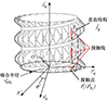 |
图5 不完整齿轮副接触点位置 |
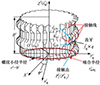 |
图6 不完整齿轮副接触线长度 |
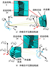 |
图7 有限元模型 |
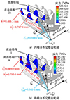 |
图8 接触应力云图 |
3.2 接触线长度
如图 6所示, 不完整齿轮副的接触线被分割成多条不连续的线段, 此时不完整齿轮副的接触线长度为各个齿牙上的接触线长度之和。图 6中, hqji为齿牙jiR×q上的接触线,  分别为接触线hqji上端点和下端点的ziR轴坐标。则hqji值为
 (23)
(23)
由图 6得 和
和 的值为
的值为
 (24)
(24)
式中, uqji和θqji为接触点在滚柱坐标系上的曲面坐标, 其值为
 (25)
(25)
 (26)
(26)
 (27)
(27)
式中, 滚柱坐标系 下的接触点坐标
 的求法为
的求法为
 (28)
(28)
由图 6和(24)~(28)式得到不完整齿轮副在直齿结构jiR上的接触线长度Lji值为
 (29)
(29)
4 模型验证
根据表 1提供的结构参数, 建立如图 7所示的不完整齿轮副的有限元模型, 滚柱直齿、内齿圈与外齿圈的弹性模量和泊松比分别为210 GPa和0.3。
对于内啮合不完整齿轮副有限元模型, 如图 7a)所示, 在滚柱直齿轴的周向方向施加旋转角度φ1=-0.12 rad,分成3个增量步完成,并约束zR1轴的其余自由度;向内齿圈zRg1轴的周向施加50 N·mm的扭矩, 并约束zRg1轴的其余自由度。对直齿结构26与直齿结构1的网格进行细化并在其内齿圈啮合侧设置3个接触对。
对于外啮合不完整齿轮副有限元模型, 如图 7b)所示, 在滚柱直齿zR2轴的周向方向施加旋转角度φ2=-0.12 rad,分成3个增量步完成, 并约束zR2轴的其余自由度; 向滚柱直齿zWt2轴的周向施加数值为-50 N·mm的扭矩, 并约束zWt2轴的其余自由度。对直齿结构#26与直齿结构#1的网格进行细化并在其外齿圈啮合侧设置3个接触对。通过建立不完整齿轮副的有限元模型, 求得各个旋转角度下的接触应力云图, 并测量得到直齿结构26的啮合半径与接触线长度。其中滚柱直齿旋转角度为-0.02 rad的接触应力云图如图 8所示。
表 2~3对比了有限元模型与不完整齿轮副模型对直齿结构26的计算结果, 分别展示了内外啮合不完整齿轮副的啮合半径与接触线长度数据。
由表 2~3可知, 不完整齿轮副啮合半径随滚柱直齿旋转角度绝对值的增大而增大, 接触线长度随滚柱直齿旋转角度绝对值的增大而减小; 不完整齿轮副啮合模型与有限元模型的啮合半径最大相对误差最大为0.12%, 接触线长度最大相对误差为1.01%, 在应允的误差限范围内。综上, 本文所建立的不完整齿轮副啮合模型能用作计算不完整齿轮副的接触点位置与接触线长度。
不完整齿轮副结构参数
内啮合不完整齿轮副计算结果对比
外啮合不完整齿轮副计算结果对比
5 结构参数影响分析
设不完整齿轮副顺时针啮合的啮合半径rimR与滚柱直齿分度圆半径riR相等, 滚柱直齿上各直齿结构上的接触线长度为 。
。
研究滚柱直齿齿廓起始角度φiR0、滚柱直齿螺纹起始角度θi0和齿宽Bi对 和
和 的影响。
的影响。
5.1 滚柱直齿齿廓起始角度
不完整齿轮副的齿宽 , 不完整齿轮副除齿宽与齿廓起始角度外均用表 1参数。
由图 4可知, 滚柱直齿齿廓起始角度 。则滚柱直齿齿廓起始角度从0~2π/ZiR时, 内啮合与外啮合不完整齿轮副中
 和
和 的变化如图 9所示。
由图 9可知,  和
和 不会随着滚柱直齿齿廓起始角度变化而变化。
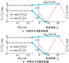 |
图9 φiR0对 |


5.2 滚柱直齿螺纹起始角度
不完整齿轮副的齿宽Bi=5 mm(i=1, 2), 不完整齿轮副除齿宽与螺纹起始角度以外均采用表 1的结构参数。
滚柱直齿螺纹起始角度θi0∈[0, 2π), 则滚柱直齿齿廓起始角度从0至2π时, 内啮合与外啮合不完整齿轮副中 和
和 的变化如图 10所示。
由图 10可知,  和
和 不会随着滚柱直齿螺纹起始角度变化而变化。
当滚柱直齿齿廓起始角度φiR0或滚柱直齿螺纹起始角度θi0其中一个值保持不变时, 另一个值的变化不会影响 和
和 的值, 因此滚柱直齿齿廓与滚柱直齿螺纹的相对起始角度不会对
 和
和 的值产生影响。
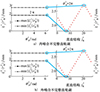 |
图10 θi0对 |


5.3 齿宽
不完整齿轮副除齿宽以外均采用表 1的结构参数。当不完整齿轮副齿宽从2~10 mm时, 内啮合与外啮合不完整齿轮副中 和
和 的变化如图 11所示。
由图 11可知, 当齿宽Bi从 增加至
增加至 的过程中,
的过程中,  的值呈现先增加后不变的趋势, 而
 的值呈现先不变再增加的趋势。且当不完整齿轮副齿宽为滚柱螺纹导程的整数倍时, 即
 时,
时,  值与
值与 值相等。说明当不完整齿轮副齿宽为滚柱螺纹导程的整数倍时, 同一啮合半径下, 任一直齿结构上的接触线长度均相等。
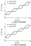 |
图11 Bi对 |

6 结论
1) 结合滚柱螺纹方程、渐开线方程与坐标变换关系, 建立了PRSM内啮合和外啮合不完整齿轮副在固定坐标系下的曲面方程; 结合不完整齿轮副的曲面方程与齿轮啮合原理, 求解出不完整齿轮副的接触点位置和接触线长度。
2) 不完整齿轮副在同一啮合半径rimR下, 各直齿结构上的接触线长度的最大值 与最小值
与最小值 不受滚柱直齿齿廓起始角度φiR0与滚柱直齿螺纹起始角度θi0的影响。
3) 当不完整齿轮副齿宽Bi为滚柱螺纹导程LiR的整数倍时, 同一啮合半径下, 任一直齿结构上的接触线长度均相同。在PRSM不完整齿轮副的设计中, 建议将不完整齿轮副齿宽Bi设计为滚柱螺纹导程LiR的整数倍。
References
- BLINOV D S, RYAKHOVSKY O A, SOKOLOV P A. Numerical method of determining the point of initial thread contact of two screws with parallel axes and different thread inclinations[J]. Scientific Journal of Murmansk State Technical University, 1996(3): 93–97 [Google Scholar]
- RYAKHOVSKIY O A, SOROKIN F D, MAROKHIN A S. Calculation of radial displacements of nut and rollers axes and the position of a contact between the nut and the roller thread in an inverted planetary roller screw mechanism[J]. Proceedings of Higher Educational Institutions, Machine Building, 2013(11): 12–19 [Google Scholar]
- FEDOSOVSKY M E, ALEKSANIN S A, PUCTOZEROV R V. Use of numerical method for determination of contact points position in roller screw threads[J]. Biosciences Biotechnology Research Asia, 2015, 12(1): 721–730. [Article] [Google Scholar]
- FU Xiaojun. Theoretical and experimental study on meshing and kinematic characteristics of planetary roller screw pair[D]. Xi'anNorthwestern Polytechnical University, 2018 (in Chinese) [Google Scholar]
- JONES M H, VELINSKY S A. Contact kinematics in the roller screw mechanism[J]. Journal of Mechanical Design, 2013, 135(5): 051003. [Article] [CrossRef] [Google Scholar]
- WEI Zhenxing, YANG Jiajun, ZHU Jisheng, et al. Optimized analysis on structural parameter for planetary roller screw[J]. Journal of Mechanical Transmission, 2011, 35(6): 44–47 (in Chinese) [Google Scholar]
- ZAVYALOV V S, FEDOSOVSKY M E, MALTSEVA N K, et al. Standardization and control of thread parameters of a roller-screw gear[J]. IOP Conference Series: Materials Science and Engineering, 2021, 1064(1): 012046. [Article] [Google Scholar]
- MA Shangjun, LIU Geng, TONG Ruiting, et al. Kinematic analysis of an inverted planetary roller screw considering roller pitch circle mismatch[J]. Chinese Journal of Mechanical Engineering, 2014, 25(11): 1421–1426 (in Chinese) [Google Scholar]
- JONES M H, VELINSKY S A. Kinematics of roller migration in the planetary roller screw mechanism[J]. Journal of Mechanical Design, 2012, 134(6): 061006. [Article] [Google Scholar]
- XING M C, ZHANG B H, DENG P, et al. A comprehensive analysis of contact kinematics for planetary roller screw mechanism[J]. Tribology International, 2023, 179: 108127. [Article] [Google Scholar]
- FU X J, LIU G, TONG R T, et al. A nonlinear six degrees of freedom dynamic model of planetary roller screw mechanism[J]. Mechanism and Machine Theory, 2018, 119: 22–36. [Article] [Google Scholar]
- FU X J, LIU G, MA S J, et al. Kinematic model of planetary roller screw mechanism with run-out and position errors[J]. Journal of Mechanical Design, 2018, 140(3): 032301. [Article] [Google Scholar]
- FU X J, LIU G, MA S J, et al. An efficient method for the dynamic analysis of planetary roller screw mechanism[J]. Mechanism and Machine Theory, 2020, 150: 103851. [Article] [Google Scholar]
- XU Qianjin, MA Shangjun, NIU Maodong, et al. Dynamic load distribution of roller thread considering gear pair meshing excitation[J]. Journal of South China University of Technology, 2023, 51(11): 119–130 (in Chinese) [Google Scholar]
- MA Tenglong, MA Shangjun, WU Linping, et al. Dynamic contact load characteristics of synchromesh between screw pair and gear pair in the planetary roller screw[J]. Journal of Xi'an Jiaotong University, 2022, 56(10): 11–21 (in Chinese) [Google Scholar]
- LIU Geng, MA Shangjun, FU Xiaojun. Planetary roller screw mechanism transmission-meshing theory[M]. Beijing: Science Press, 2018 (in Chinese) [Google Scholar]
All Tables
All Figures
|
图1 内啮合不完整齿轮副坐标系 |
| In the text | |
|
图2 外啮合不完整齿轮副坐标系 |
| In the text | |
|
图3 滚柱直齿结构组成 |
| In the text | |
|
图4 滚柱直齿零件坐标系 |
| In the text | |
|
图5 不完整齿轮副接触点位置 |
| In the text | |
|
图6 不完整齿轮副接触线长度 |
| In the text | |
|
图7 有限元模型 |
| In the text | |
|
图8 接触应力云图 |
| In the text | |
|
图9 φiR0对 |
| In the text | |
|
图10 θi0对 |
| In the text | |
|
图11 Bi对 |
| In the text | |
Current usage metrics show cumulative count of Article Views (full-text article views including HTML views, PDF and ePub downloads, according to the available data) and Abstracts Views on Vision4Press platform.
Data correspond to usage on the plateform after 2015. The current usage metrics is available 48-96 hours after online publication and is updated daily on week days.
Initial download of the metrics may take a while.