| Issue |
JNWPU
Volume 43, Number 1, February 2025
|
|
|---|---|---|
| Page(s) | 181 - 188 | |
| DOI | https://doi.org/10.1051/jnwpu/20254310181 | |
| Published online | 18 April 2025 | |
A face gear grinding method and its experimental verification using cylindrical internal gear grinding machine
基于圆柱内齿轮磨齿机磨削面齿轮方法及试验验证
1
School of Mechatronics Engineering, Hennan University of Science and Technology, Luoyang 471003, China
2
Longmen Laboratory, Luoyang 471003, China
3
School of Mechanical Engineering, Northwestern Polytechnical University, Xi'an 710072, China
4
AECC Zhongchuan Transmission Machinery Co., Ltd., Changsha 410200, China
Received:
18
January
2024
According to the structure of a machine tool, the mathematical model of face gear grinding with a disc grinding wheel is established. The face gear tooth surface equation that contains the machine tool parameter errors is derived, and the influence of the parameter errors on the topological deviation of the tooth surface is analyzed. The experiments on face gear grinding are completed with the cylindrical internal gear grinding machine and detected in the gleason gear detection center. The maximum tooth surface deviation is -24.6 μm, verifying the feasibility of the proposed grinding method and the correctness of the machine tool parameter adjustment method. The use of the general cylindrical internal gear grinding machine to grind face gears without special face gear machine tool is of great significance for the promotion of face gears and the reduction of manufacturing cost.
摘要
提出在通用圆柱内齿轮磨齿机上磨削面齿轮的加工方法。根据机床结构, 建立了碟形砂轮磨削加工面齿轮数学模型, 推导了含机床参数误差的面齿轮齿面方程, 分析了机床参数误差对齿面拓扑偏差的影响规律。在圆柱内齿轮磨齿机上完成了面齿轮磨削试验, 并在Gleason齿轮检测中心检测, 齿面偏差最大值为-24.6 μm, 验证了所提出加工方法的可行性和调整机床参数方法的正确性。采用通用圆柱内齿轮磨齿机磨削面齿轮无需专用的面齿轮加工机床, 对于面齿轮的推广及降低制造成本都具有重要意义。
Key words: face gear / cylindrical internal gear grinding machine / grinding / disc wheel / error analysis
关键字 : 面齿轮 / 圆柱内齿轮磨齿机 / 磨削加工 / 碟形砂轮 / 误差分析
© 2025 Journal of Northwestern Polytechnical University. All rights reserved.
 This is an Open Access article distributed under the terms of the Creative Commons Attribution License (https://creativecommons.org/licenses/by/4.0), which permits unrestricted use, distribution, and reproduction in any medium, provided the original work is properly cited.
面齿轮传动具有结构紧凑、安装调整方便、传动比大等优点, 在航空、车辆等工业领域具有广阔的应用前景[1–2]。Litvin及其团队[3–5]与美国军工企业合作, 已经生产出可用于飞机传动机构的高精度面齿轮。国内学者对面齿轮加工开展了许多研究, 如王延忠等[6–7]设计了面齿轮专用加工机床并分析碟形砂轮修整装置产生误差的原因; 郭辉等[8–10]研究了面齿轮磨齿偏差的形成规律; 彭先龙等[11–13]提出一种基于四轴数控机床磨削面齿轮的加工方法并对碟形砂轮磨削加工误差进行了理论分析; 李大庆[14]提出了面齿轮磨削加工在通用数控加工中心上的实现方法。
面齿轮的精密制造目前依赖于专用磨齿机床, 磨齿成本高。面齿轮的磨齿加工方法主要分为单齿展成磨削和蜗杆砂轮磨削。蜗杆砂轮磨削效率很高, 但蜗杆砂轮修整困难, 修整效率低; 分度展成方法将砂轮修整成渐开线圆柱齿轮的齿廓, 修整效率高, 但加工效率偏低, 主要用于小批量加工。
本文提出在现有的圆柱内齿轮磨齿机床上, 采用碟形砂轮, 通过砂轮架的插补运动磨削面齿轮, 解决硬齿面面齿轮的精密加工问题。建立了圆柱内齿轮磨齿机磨削面齿轮展成加工模型; 分析了砂轮安装误差、砂轮架安装误差及砂轮臂几何长度误差对齿面拓扑形状的影响, 为机床参数误差修正提供了依据; 通过试验验证了加工方法的可行性和调整机床参数方法的正确性。
1 圆柱内齿轮磨齿机磨削面齿轮运动分析
1.1 碟形砂轮磨齿原理
渐开线碟形砂轮的截面形状为产形轮的一个单齿截面, 碟形砂轮的磨齿过程实质上是模拟产形轮与面齿轮的啮合过程。图 1表示了碟形砂轮和产形轮的几何关系。图中, rps是产形轮齿顶圆半径; E是砂轮中心与产形轮中心距离; φc, φg分别为产形轮、面齿轮加工的摆角。
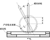 |
图1 碟形砂轮磨齿原理 |
碟形砂轮绕产形轮轴线旋摆的速度ωc与面齿轮的转速ωg之间满足以下关系
式中, Zc和Zg分别为产形轮和面齿轮的齿数。
1.2 圆柱内齿轮磨齿机结构
圆柱内齿轮磨齿机结构布局如图 2所示, 机床共有5个运动轴, 即X, Y, Z移动轴和A, B旋转轴。砂轮架可沿Z向和Y向移动, 砂轮臂安装在砂轮架上并随A轴转动, 碟形砂轮安装在砂轮臂上随主轴C轴旋转做切削运动。回转工作台可沿X轴移动, 工件安装在B轴上并随B轴转动。
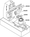 |
图2 圆柱内齿轮磨齿机床结构 |
1.3 面齿轮磨削展成运动
面齿轮展成过程为工件与砂轮架的相对运动, 如图 3所示。产形轮中心为Oc, 为满足砂轮的渐开线廓形绕Oc做旋摆运动, 砂轮架回转中心On的运动轨迹为圆弧OnOp。
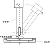 |
图3 面齿轮磨削展成运动 |
磨削加工过程中, 为了实现产形轮和面齿轮展成运动, 需要砂轮架绕A轴旋转,同时在Y, Z方向上做运动插补, 将砂轮架中心运动转换到产形轮上, 从而实现碟形砂轮模拟产形轮的旋转运动, 其运动简图如图 4所示。
 |
图4 砂轮架运动简图 |
图 4中, E是砂轮中心与产形轮中心距离, L为砂轮臂长度(砂轮架回转中心到砂轮回转中心的长度), φc为产形轮摆角也是展成过程中砂轮架摆角, 在砂轮架摆动的同时砂轮架中心从Op移动到On, 保证了产形轮与工件的正确展成位置。面齿轮磨齿加工中, 产形轮摆角φc的极限位置位于面齿轮大端齿顶和产形轮齿根啮合处。
砂轮架回转中心在机床Z方向的插补位移为
式中, a=E+L。
砂轮架回转中心在机床Y方向的插补位移为
与此同时, 碟形砂轮通过在X方向上的往复运动实现整个齿宽的磨削加工, 如图 5所示, R1和R2为面齿轮内外半径, 机床回转工作台X轴行程DX需大于面齿轮齿宽。面齿轮的转动角度φg满足(1)式的滚比关系。
 |
图5 沿齿长方向的进给运动 |
通过圆柱内齿轮磨齿机床X, Y, Z坐标轴方向上的移动, 以及绕B轴和A轴的旋转,这5种运动的合成即可实现面齿轮碟形砂轮的磨齿加工。
2 面齿轮齿面展成数学模型
依据碟形砂轮磨削面齿轮原理, 砂轮轴向廓形和产形轮的廓形一致, 砂轮齿面方程为
式中: E是砂轮中心与产形轮中心距离; θ0为刀具齿槽对称线到渐开线起始点的角度; θc是渐开线上一点的角度参数; rb为产形轮基圆半径; uc为砂轮齿面某一点的轴向参数; “±”号分别对应于砂轮齿槽两侧渐开线。
图 6为碟形砂轮加工坐标系, 砂轮架动坐标系Sp与砂轮架固连, 在磨削过程中, 砂轮架动坐标系Sp与砂轮架一起绕产形轮中心Oc旋转, φc为产形轮摆角; 机床固定坐标系Sn与加工机床固连; 砂轮坐标系Ss与砂轮固连, L为砂轮臂长度(即砂轮架回转中心到砂轮回转中心的长度)。
 |
图6 砂轮架加工坐标系 |
从砂轮坐标系Ss到砂轮架动坐标系Sp的转换矩阵为
从砂轮架动坐标系Sp到机床固定坐标系Sn的转换矩阵为
式中, φc为产形轮摆角; a=E+L。
图 7为面齿轮展成坐标系, 面齿轮动坐标系Sg与回转工作台固连, φg为面齿轮转角; 面齿轮初始坐标系Sm与机床固连。
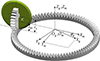 |
图7 面齿轮展成坐标变换 |
从机床固定坐标系Sn到面齿轮初始坐标系Sm的转换矩阵为
从面齿轮初始坐标系Sm到面齿轮动坐标系Sg的转换矩阵为
式中, φg=icgφc。
将砂轮齿面方程经坐标变化表示在面齿轮动坐标系Sg中,如(9)式所示。
面齿轮磨齿展成加工时, 刀具齿面与被加工面齿轮齿面满足啮合方程
图 8所示为齿面旋转投影面, 面齿轮齿面上任意一点在旋转投影面上的二维坐标(R, Z), 满足位置方程[15]
 |
图8 齿面旋转投影面 |
通过求解非线性方程组(10)~(11)式, 确定3个未知参数(θc, uc, φc), 从而求出该点齿面坐标值。
以上推导的面齿轮齿面与插齿齿面完全一致。但是, 实际加工过程中, 机床的一些设定参数与机床本身的实际参数存在偏差, 因此, 需要进行机床参数误差分析。
3 机床参数误差分析
3.1 机床参数误差影响因素
在面齿轮展成磨削过程中, 砂轮、砂轮架与机床相对位置的偏差, 导致产形轮的实际运动与理论产形轮运动存在偏差, 从而影响面齿轮加工精度。如图 9所示, 机床砂轮架回转中心与砂轮回转中心的位置误差, 导致砂轮臂的安装误差Δy; 砂轮修整时, 砂轮中垂线与金刚轮中垂线的侧偏, 导致修整后砂轮的安装误差Δs; 砂轮架臂长度的实际值与设计值L的误差, 导致砂轮臂长度误差Δl。
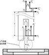 |
图9 砂轮架垂直时机床位置误差关系 |
根据图 9中的坐标系关系可写出坐标转换矩阵, 分别为
将(12)~(13)式替换(5)~(6)式, 包含机床参数误差的面齿轮齿面位矢可表示为
3.2 齿面偏差计算
面齿轮的齿面分两部分, 因过渡曲面不参与啮合, 本文对面齿轮工作齿面进行分析。面齿轮工作齿面检测区域取齿顶齿根收缩量5%齿高, 大端小端收缩量10%齿宽。工作齿面区域可以划分成5行、9列的节点, 如图 10所示。
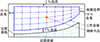 |
图10 齿面网格点划分 |
根据齿面方程, 可求得各网格位置的理论齿面点位矢rg(i, j)与法矢ng(i, j), 其中i=1, 2, …, 5, j=1, 2, …, 9。定义实际齿面上各网格点位矢为Rv(i, j), 选取齿面网格中点作为基准点, 实测点与理论齿面重合, 即该点误差为零。齿面偏差为实际齿面偏离理论齿面的距离, 可表示为
式中, 
3.3 齿面偏差分析
面齿轮磨削加工参数如表 1所示。
面齿轮副的基本参数
图 11为砂轮臂安装误差Δy引起的齿面偏差。从偏差变化结果看, 砂轮臂安装误差Δy主要引起压力角偏差, 且左右齿面压力角变化相反。其中增大Δy将导致左齿面压力角变小, 右齿面压力角变大; 减小Δy将导致左齿面压力角变大, 右齿面压力角变小。
 |
图11 砂轮臂安装误差对齿面影响 |
图 12为砂轮安装误差Δs引起的齿面偏差。从偏差变化结果看, 砂轮安装误差Δs主要引起面齿轮螺旋角变化, 增大Δs将导致面齿轮齿向呈右旋走向; 减小Δs将导致面齿轮齿向呈左旋走向。
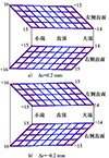 |
图12 砂轮安装误差对齿面影响 |
图 13为砂轮臂长度误差Δl引起的齿面偏差。从偏差变化结果看, 砂轮臂长度误差Δl主要引起齿面扭转偏差, 同时还有压力角偏差, 其中小端齿根影响最大。增大Δl将导致左右齿面整体压力角增大; 减小Δl将导致左右齿面整体压力角减小。
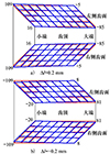 |
图13 砂轮臂长度误差对齿面影响 |
可通过调整这3个参数来修正齿面加工误差, 建立砂轮臂安装误差Δy、砂轮安装误差Δs、砂轮臂长度误差Δl对齿面拓扑敏感性矩阵[16], 根据齿面误差计算机床修正量。
4 面齿轮磨削加工试验
在圆柱内齿轮磨齿机上磨削加工面齿轮, 参数见表 1。图 14为圆柱内齿轮磨齿机, 图 15为面齿轮磨削加工图, 图 16为在Gleason650GMS齿轮检测中心上对磨削后的面齿轮进行误差检测。
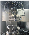 |
图14 圆柱内齿轮磨齿机 |
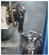 |
图15 面齿轮磨削加工 |
 |
图16 面齿轮检测 |
图 17为面齿轮齿面拓扑误差检测结果。左齿面的误差为-87~176 μm,右齿面的误差为-98.6~166.8 μm, 偏差体现在压力角和螺旋角上。
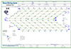 |
图17 初步磨齿的齿面偏差 |
根据齿面误差计算得到Δy, Δs, Δl修正量分别为0.09, 0.13, -0.32 mm。
图 18为修正后的实际齿面与理论齿面偏差图, 左齿面的误差为-24.6~23.8 μm、右齿面误差为-21.4~17 μm, 且最大偏差远离接触区。试件检测结果验证了加工方法的可行性和调整机床参数方法的正确性。
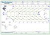 |
图18 修正后的齿面偏差 |
5 结论
本文获得的主要结论如下:
1) 根据机床结构及蝶形砂轮展成磨削面齿轮的原理, 建立了圆柱内齿轮磨齿机与面齿轮展成运动数学模型。
2) 分析了砂轮安装误差、砂轮架安装误差及砂轮臂几何长度误差对齿面拓扑形状的影响。
3) 在圆柱内齿轮磨齿机上完成了面齿轮磨齿试验并进行误差检测, 理论和试验证明, 在数控内齿轮磨齿机上磨削面齿轮没有原理性误差, 通过调整机床参数, 能够有效地修正齿面误差。4) 本文提出了圆柱内齿轮磨齿机磨削面齿轮的加工方法。解决了面齿轮加工依赖于专用机床的问题, 对于面齿轮的推广及降低制造成本都具有重要意义。
References
- WANG Zhi, SHI Zhaoyao, LIU Jianwei, et al. Simulation of orthogonal face gear proceeding[J]. Journal of Beijing University of Technology, 2012, 38(7): 1004–1007 (in Chinese) [Google Scholar]
- TANG Jinyuan, YIN Feng, CHEN Xingming. The principle of profile modified face-gear grinding based on disk wheel[J]. Mechanism and Machine Theory, 2013, 70: 9–15. [Article] [Google Scholar]
- LITVIN F L, CHEN Y J, HEATH G F, et al. Apparatus and method for precision grinding face gear: US, 6. 146. 235[P]. 2000-11-14 [Google Scholar]
- LITVIN F L, ALFONSO Fuentes, MATT Howkins. Design, generation and TCA of new type of asymmetric face-gear drive with modified geometry[J]. Computer Methods in Applied Mechanics and Engineering, 2001, 190(43/44): 5837–5865. [Article] [Google Scholar]
- LITVIN F L, GONZALEZ-PEREZ I, FUENTES A, et al. Design, generation and stress analysis of face-gear drive with helical-pinion[J]. Computer Methods in Applied Mechanics and Engineering, 2005, 194(36/37/38): 3870–3901. [Article] [Google Scholar]
- WANG Yanzhong, HOU Liangwei, LAN Zhou, et al. Research on processing method of grinding face gear with involute disc wheel[J]. Journal of Aerospace Power, 2015, 30(8): 2033–2041 (in Chinese) [Google Scholar]
- WANG Yanzhong, ZHONG Yang, HOU Liangwei, et al. Dressing method and dressing error analysis of aviation face gear grinding wheel[J]. Journal of Aerospace Power, 2017, 32(1): 120–129 (in Chinese) [Google Scholar]
- GUO H, ZHANG S Y. Grinding experiment research of face gear with CNC machine[J]. Applied Mechanics and Materials, 2014, 496: 503–506 [Google Scholar]
- GUO Hui, ZHAO Ning, XIANG Yunfei, et al. Face gear grinding method using six-axis CNC worm wheel machine[J]. Journal of Mechanical Engineering, 2015, 51(11): 186–194 (in Chinese) [Google Scholar]
- GUO Hui, ZHAO Ning, HOU Shengwen. Tooth deviation analysis and experimental research of face gear based on disk grinding wheel[J]. Journal of Northwestern Polytechnical University, 2013, 31(6): 915–920. [Article] (in Chinese) [Google Scholar]
- PENG Xianlong, FANG Zongde, SU Jinzhan, et al. Theory analysis for application grinding disk in face gear grinding[J]. Journal of Aerospace Power, 2012, 27(5): 1159–1165 (in Chinese) [Google Scholar]
- PENG Xianlong, ZHAO Penghui, HU Xiwen, et al. Grinding method for face gear based on four-axis CNC machine tool[J]. Journal of Aerospace Power, 2021, 36(5): 1113–1120 (in Chinese) [Google Scholar]
- PENG Xianlong, LI Jianhua, FANG Zongde, et al. Computer numerical controlling rules for applying grinding disk in face gear grinding[J]. Journal of Harbin Institute of Technology, 2012, 44(11): 101–104. [Article] (in Chinese) [Google Scholar]
- LI Daqing. Research on pre-control method of meshing behavior and key technologies for grinding face gear by dish wheel[D]. Zhenjiang: Jiangsu University, 2013 (in Chinese) [Google Scholar]
- CAO Xuemei, DENG Xiaozhong, NIE Shaowu. Ease-off flank topography design for aviation spiral bevel gears with higher-order transmission errors by modification of conjugate flank[J]. Journal of Aerospace Power, 2015, 30(1): 195–200 (in Chinese) [Google Scholar]
- HAN Zhengyang. Study on the forming mechanism and topological modification of face gears by power skiving[D]. Xi'an: Northwestern Polytechnical University, 2022 (in Chinese) [Google Scholar]
All Tables
All Figures
|
图1 碟形砂轮磨齿原理 |
| In the text | |
|
图2 圆柱内齿轮磨齿机床结构 |
| In the text | |
|
图3 面齿轮磨削展成运动 |
| In the text | |
|
图4 砂轮架运动简图 |
| In the text | |
|
图5 沿齿长方向的进给运动 |
| In the text | |
|
图6 砂轮架加工坐标系 |
| In the text | |
|
图7 面齿轮展成坐标变换 |
| In the text | |
|
图8 齿面旋转投影面 |
| In the text | |
|
图9 砂轮架垂直时机床位置误差关系 |
| In the text | |
|
图10 齿面网格点划分 |
| In the text | |
|
图11 砂轮臂安装误差对齿面影响 |
| In the text | |
|
图12 砂轮安装误差对齿面影响 |
| In the text | |
|
图13 砂轮臂长度误差对齿面影响 |
| In the text | |
|
图14 圆柱内齿轮磨齿机 |
| In the text | |
|
图15 面齿轮磨削加工 |
| In the text | |
|
图16 面齿轮检测 |
| In the text | |
|
图17 初步磨齿的齿面偏差 |
| In the text | |
|
图18 修正后的齿面偏差 |
| In the text | |
Current usage metrics show cumulative count of Article Views (full-text article views including HTML views, PDF and ePub downloads, according to the available data) and Abstracts Views on Vision4Press platform.
Data correspond to usage on the plateform after 2015. The current usage metrics is available 48-96 hours after online publication and is updated daily on week days.
Initial download of the metrics may take a while.