| Issue |
JNWPU
Volume 44, Number 1, February 2026
|
|
|---|---|---|
| Page(s) | 177 - 184 | |
| DOI | https://doi.org/10.1051/jnwpu/20264410177 | |
| Published online | 27 April 2026 | |
Three-wire measurement calculation method for pitch diameter of external threads in planetary roller screws
行星滚柱丝杠外螺纹中径三针测量计算方法
School of Mechanical Engineering, Northwestern Polytechnical University, Xi'an 710072, China
Received:
13
May
2025
Abstract
To improve the measurement accuracy of the external thread diameter in planetary roller screw mechanisms (PRSM) and to mitigate the influence of machining errors on the results of the traditional three-point measurement method, a contact equation between the measured thread and the measuring needle is established, using a set of calculation equations for the external thread diameter that incorporate machining errors, which are then solved. By considering the critical factors, including pitch deviation, half-thread thickness deviation and thread side angle deviation, contact points are predicted by using the assembly relationship between the thread and the measuring needle. The contact equation between the measured thread and the measuring needle is derived by using the principle of continuous surface tangency. The calculated values of the thread diameter in the three-point method, with and without considering machining errors, are solved separately, and the impact of thread machining errors on the correction values of the external thread diameter is investigated. The results reveal the following correlation between thread machining errors and the correction values of the diameter: the increase in pitch deviation results in a monotonically decreasing correction value; the increase in half-thread thickness deviation leads to a monotonically increasing correction value; under the simultaneous deviation of both thread side angles, the correction value exhibits a non-linear trend of initially decreasing and then increasing with the increasing of deviation angle; in asymmetric deviation conditions on one side, while maintaining a similar non-linear variation trend, the variation amplitude is significantly reduced.
摘要
为提高行星滚柱丝杠(PRSM)外螺纹中径的测量精度, 解决加工误差对传统三针法测量结果的影响, 建立被测螺纹与量针的接触方程和计入加工误差的外螺纹中径计算方程组并进行求解。综合考虑螺距偏差、半牙厚偏差及牙侧角偏差等关键因素, 通过螺纹-量针装配关系预测接触点。运用曲面连续相切原理推导出被测螺纹与测量量针的接触方程, 分别求解忽略/计入加工误差时的三针法中径计算值, 研究了螺纹加工误差对外螺纹中径修正值的影响。结果表明, 螺纹加工误差与中径修正值存在以下关联规律: 螺距偏差增大导致中径修正值单调递减; 半牙厚偏差增加导致修正值单调递增; 双侧牙侧角同步偏差条件下, 中径修正值随偏差角增大呈现先减小后增大的非线性变化趋势; 单侧非对称偏差工况中, 虽保持相似的非线性演变趋势, 但变化幅度显著下降。
Key words: planetary roller screw mechanism (PRSM) / machining errors / three-wire method / pitch diameter of external threads
关键字 : 行星滚柱丝杠 / 加工误差 / 三针法 / 外螺纹中径
© 2026 Journal of Northwestern Polytechnical University. All rights reserved.
 This is an Open Access article distributed under the terms of the Creative Commons Attribution License (https://creativecommons.org/licenses/by/4.0), which permits unrestricted use, distribution, and reproduction in any medium, provided the original work is properly cited.
行星滚柱丝杠(planetary roller screw mechanism, PRSM)是一种通过螺纹啮合实现旋转-直线运动转换的精密传动装置,其核心组件包括丝杠、螺母、滚柱及保持架等。其中,丝杠与滚柱为外螺纹制件,其螺纹加工精度直接影响PRSM的传动性能与使用寿命[1]。PRSM凭借高承载、高精度、长寿命等优势,广泛应用于航空航天、精密机床、医疗器械及武器装备等[2-5]领域。然而,PRSM外螺纹中径的精确测量仍是当前面临的技术难题,直接影响螺纹加工质量的评估与工艺优化。
三针法作为外螺纹中径测量的主流方法,近年来在算法优化、设备集成及模型拓展等方面取得显著进展。在算法优化方面,肖剑等[6]提出基于改进哈里斯鹰算法的螺纹中径测量方法,提升了图像处理效率;李明炜等[7]开发了通用视觉算法,实现了多牙型外螺纹的兼容测量。在设备集成方面,Shchurov[8]利用三坐标测量机(CMM)点云计算虚拟中径;王飞杰等[9]通过Visual Basic编程实现了三针法中径值的快速求解。在模型拓展方面,林葵等[10]提出扩展虚拟三针法牙廓测量模型;陈盛等[11]结合样条插值与回归滤波建立了二维点云中径计算框架;Kosarevsky等[12]利用广义霍夫变换提取螺纹剖面切圆求解中径;李奎等[13]提出了一种基于虚拟三针法的螺纹中径测量方法,通过建立虚拟三针法测量螺纹中径的理论计算模型,对提取的螺纹轮廓进行拟合获取中径值;Gadelmawla[14]采用可视化方法获得了螺纹牙廓图像,根据螺纹底径信息计算中径线与底径线的偏差,结合两者最终得到螺纹中径。
然而,现有方法普遍依赖理论螺距、牙型角等螺纹理想参数,未系统考虑加工误差对中径测量的影响,导致测量结果与实际工况存在显著偏差。此外,国内PRSM螺纹加工精度检测技术仍落后于国际先进水平,难以满足高端装备对精密螺纹传动件的性能需求[15-16]。
针对上述问题,本文基于外螺纹接触方程,推导了忽略与计入加工误差条件下的三针法外螺纹中径值计算公式,构建了包括牙型角误差、螺距误差与半牙厚误差的数学模型,并通过案例验证了修正方法的有效性。研究结果为提升PRSM外螺纹中径测量精度提供了理论依据,对推动PRSM精密螺纹加工技术的发展有着重要意义。
1 螺旋曲面方程
如图 1所示, oi-xiyizi(i=S, R)分别表示行星滚柱丝杠中丝杠和滚柱的坐标系。建立位于螺距螺旋线Γi上的截面坐标系o′i-uiviwi, 其wi轴与zi轴平行。ri和λi0分别为零件的名义半径和螺旋升角。ΓiU和ΓiB分别是螺纹的上、下螺旋曲面。
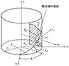 |
图1 测量零件坐标系oi-xiyizi和截面坐标系o′i-uiviwi |
根据齐次变换原理, o′i-uiviwi向oi-xiyizi的变换矩阵T′i可写为
 (1)
(1)
式中, Li代表螺纹导程, 可表示为
 (2)
(2)
丝杠和滚柱的螺纹轮廓分别如图 2a)~2b)所示, βi (i=S, R)为牙侧角, ai和bi分别代表螺纹的齿顶高和齿根高, ci代表半牙厚。P代表螺纹螺距, rPR代表滚柱螺纹轮廓半径。
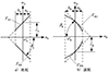 |
图2 丝杠和滚柱的螺纹轮廓 |
基于螺纹轮廓参数化建模与(1)式坐标系变换关系, 可得被测零件在工件坐标系oi-xiyizi中的螺旋曲面方程为
 (3)
(3)
式中
 (4)
(4)
 (5)
(5)
式中, ui, θi代表曲面坐标; 下标i=S, R分别对应丝杠和滚柱。
当ξi=1时, (3)式表示上螺旋曲面的方程, 当ξi=-1时, (3)式表示下螺旋曲面的方程。
如图 3所示, 建立量针-工件接触点局部坐标系op1-xp1yp1zp1及op2-xp2yp2zp2, 推导得到量针接触面方程为
 (6)
(6)
 (7)
(7)
 |
图3 量针与测量零件接触点零件坐标系op1-xp1yp1zp1及op2-xp2yp2zp2 |
式中:dp为量针标称直径; θpj为接触点周向坐标(j=1, 2)。
考虑实际加工误差的装配关系时, 应对螺旋曲面方程进行误差修正, 修正后的螺旋曲面方程为
 (8)
(8)
式中
 (9)
(9)
 (10)
(10)
式中:Δci1, Δci2分别为上/下螺旋面半牙厚误差; Δβi1, Δβi2分别为上/下螺旋曲面侧牙侧角误差; ΔPi为螺距误差。
当ξi=1时, (8)式表示上螺旋曲面的方程, 当ξi=-1时, (8)式表示下螺旋曲面的方程。
2 综合修正值模型
2.1 坐标系
在忽略加工误差的理想状态下, 量针与工件的位置关系如图 4~5所示。建立工件固定坐标系oi-xiyizi, 其中zi轴与工件轴线重合, xi轴平行于工件轴线。量针与工件接触点处的局部坐标系分别记为op1-xp1yp1zp1和op2-xp2yp2zp2。
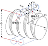 |
图4 忽略加工误差时整体坐标系装配关系 |
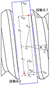 |
图5 忽略加工误差坐标系装配关系及接触点几何关系 |
全局坐标系向局部坐标系的变换矩阵可表示为
 (11)
(11)
式中
 (12)
(12)
 (13)
(13)
 (14)
(14)
式中:i=S, R分别对应丝杠与滚柱; j=1, 2表示接触点编号; mi为量针轴线间距; φi为xi轴相对于xp轴的轴线夹角; L为接触点至xioiyi平面的法向距离。
考虑加工误差时的整体坐标系装配关系如图 6~7所示, 此时变换矩阵需引入误差项。
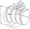 |
图6 考虑加工误差时整体坐标系装配关系 |
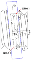 |
图7 考虑加工误差坐标系装配关系及接触点几何关系 |
全局坐标系向局部坐标系的变换矩阵可表示为
 (15)
(15)
式中
 (16)
(16)
 (17)
(17)
 (18)
(18)
式中: L1, L2分别为接触点1, 2至xioiyi平面的法向距离; Δmi为oi-xiyizi在zi轴方向上的偏移量; φi为xi轴相对于xp1轴的轴线夹角。
2.2 接触方程
忽略加工误差时, 通过(11)式可得螺纹曲面在局部坐标系的方程及法向量。
 (19)
(19)
 (20)
(20)
量针的外法线向量可表示为
 (21)
(21)
接触点需满足以下约束条件
 (22)
(22)
 (23)
(23)
 (24)
(24)
 (25)
(25)
 (26)
(26)
 (27)
(27)
 (28)
(28)
 (29)
(29)
式中:Px代表接触点之间的距离在yp2op2zp2平面上的投影;M代表量针测量值。
联立(22)~(29)式可求解理想丝杠外螺纹中径值。
考虑加工误差时, 通过(15)式可得螺纹曲面在局部坐标系的方程及法向量为
 (30)
(30)
 (31)
(31)
扩展的接触约束方程组为
 (32)
(32)
 (33)
(33)
 (34)
(34)
 (35)
(35)
 (36)
(36)
 (37)
(37)
 (38)
(38)
 (39)
(39)
 (40)
(40)
 (41)
(41)
 (42)
(42)
 (43)
(43)
 (44)
(44)
 (45)
(45)
联立(32)~(45)式可求解得到误差修正后的外螺纹中径值。
3 实验与结果
本文选取丝杠理想中径为19.5 mm、滚柱理想中径为6.5 mm的PRSM样机作为实验对象。以丝杠为例(见图 8),采用轮廓仪测量丝杠、滚柱几何参数得到丝杠、滚柱螺纹放大图(见图 9),其关键几何参数如表 1~2所示,包括量针测量值M、螺距、牙型角等。样机的加工误差数据如表 3~4所示,涵盖了螺距偏差、牙型角偏差等关键误差项。
 |
图8 三针法测量装置结构图 |
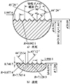 |
图9 外螺纹轮廓仪扫描图 |
丝杠结构参数
滚柱结构参数
丝杠样件实测误差
滚柱样件实测误差
基于上述参数,本文通过整合(22)~(29)式与(30)~(45)式构建了丝杠外螺纹中径的参数化计算模型。该模型通过编程实现了丝杠外螺纹中径的自动化求解,其计算流程包括:
1) 输入螺纹几何参数及加工误差数据。
2) 基于(22)~(29)式计算理想条件下的丝杠、滚柱中径。
3) 基于(30)~(45)式输出修正后的丝杠、滚柱中径。
表 5列出了丝杠和滚柱在忽略与计入加工误差条件下的螺纹中径计算结果。对比分析表明:加工误差补偿后,丝杠外螺纹中径的偏差从4.5 μm降低至2.0 μm,滚柱外螺纹中径的偏差从4.0 μm降低至2.0 μm,验证了所提参数化计算模型的有效性。
外螺纹计算中径值
4 算例分析
4.1 螺距偏差
图 10分析了螺距偏差对理论外螺纹中径修正值的影响规律。横坐标为螺距偏差ΔP, 纵坐标为外螺纹中径修正值Δd。结果表明: 当螺距偏差从-0.2 mm增至+0.2 mm时, 外螺纹中径修正值Δd从0.2 mm线性减小至-0.2 mm。值得注意的是, 外螺纹中径值随螺距增大呈反比关系, 当螺距增加0.1 mm时, 外螺纹中径计算值降低0.8%。
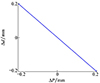 |
图10 螺距偏差对理论外螺纹中径修正值的影响规律 |
4.2 半牙厚偏差
图 11展示了半牙厚偏差对外螺纹中径修正值Δd的影响规律。横坐标为半牙厚偏差ΔcS, 纵坐标表示外螺纹中径修正值Δd。结果表明: 当半牙厚偏差ΔcS从-0.02 mm增至+0.02 mm时, 外螺纹中径修正值Δd从-0.4 mm增加到+0.4 mm; 且外螺纹中径值随半牙厚的增大呈正比关系。
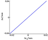 |
图11 半牙厚偏差对外螺纹中径修正值的影响规律 |
4.3 牙侧角偏差
定义单侧牙侧角变化为螺纹牙一端牙侧角存在误差, 另一端为理想值; 双侧牙侧角同步变化为螺纹牙两端相对理想值具有相同的差值。
图 12揭示了牙侧角偏差对外螺纹中径修正值Δd的作用规律。研究表明: 在双侧牙侧角同步变化条件下(见图 12a)), Δd随偏差角增大呈现先减小后增大的非线性变化趋势; 单侧牙侧角非对称变化条件下(见图 12b)), Δd虽保持类似的非线性变化趋势, 但变化幅度显著减弱。对比分析表明, 双侧牙侧角偏差对中径修正值的影响较单侧工况更为显著, 这种差异源于对称性偏差导致的几何非线性叠加效应。
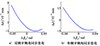 |
图12 牙侧角偏差对外螺纹中径修正值的影响规律 |
4.4 多种误差耦合作用
图 13揭示了螺距误差、牙侧角偏差、半牙厚误差耦合作用对外螺纹中径修正值Δd的作用规律。图 13中G0~G4分别代表表 6所示5种情况下的误差。
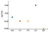 |
图13 多种误差耦合作用对外螺纹中径修正值的影响规律 |
外螺纹计算中径值
研究表明:在多种误差耦合作用下,外螺纹中径修正值变化幅度受半牙厚偏差和螺距偏差影响较大,牙侧角偏差对外螺纹中径修正值影响较小。
5 结论
本文选取丝杠理论中径为19.5 mm,滚柱理论中径为6.5 mm的PRSM产品,基于三针法测量原理和螺纹螺旋曲面方程开展了研究, 提出一种计入加工误差的外螺纹等效单一中径三针计算模型,通过建立牙型角误差(ΔβS)、螺距误差(ΔP)及半牙厚误差(ΔcS)的误差传递函数, 阐述了忽略与计入加工误差情况下的外螺纹中径计算方法,具体结论如下:
1) 螺距偏差与中径计算结果的误差呈反比关系;
2) 半牙厚偏差对中径计算结果的误差呈正比关系;
3) 牙侧角偏差对中径修正值的影响呈现显著非线性特征,其中双侧对称偏差引起的修正值较单侧非对称偏差变化幅度显著增大;
4) 在多种误差耦合作用下,外螺纹中径修正值变化幅度受半牙厚偏差和螺距偏差影响较大,牙侧角偏差对外螺纹中径修正值影响较小。
References
- Liu Siqi, Wei Peitang, Hu Rui, et al. Statistical analysis of planetary roller screw thread machining errors and comparative study at home and abroad[J]. China Mechanical Engineering, 2025, 36(8): 1–18 (in Chinese) [Google Scholar]
- Ma Shangjun, Liu Geng, Fu Xiaojun, et al. Load distribution of rollers considering errors in planetary roller screw mechanism[J]. Journal of Harbin Institute of Technology, 2015, 47(7): 98–102 (in Chinese) [Google Scholar]
- Fu X, Li X, Ma S, et al. A multi-roller static model of the planetary roller screw mechanism considering load sharing[J]. Tribology International, 2022, 173: 107648. [Article] [Google Scholar]
- Du X, Chen B, Zheng Z. Investigation on mechanical behavior of planetary roller screw mechanism with the effects of external loads and machining errors[J]. Tribology International, 2021, 154: 106689. [Article] [CrossRef] [Google Scholar]
- Fu X, Liu G, Li X, et al. Dynamic modeling of the double-nut planetary roller screw mechanism considering elastic deformations[J]. ASME Journal of Computational and Nonlinear Dynamics, 2021, 16(5): 051003. [Article] [Google Scholar]
- Xiao Jian, Zhang Kai, Gao Fan, et al. Pitch diameter measurement of threaded steel wire head based on improved HHO algorithm[J]. Journal of Electronic Measurement and Instrumentation, 2021, 35(10): 48–55 (in Chinese) [Google Scholar]
- Li Mingwei, Gan Wenlong, Yan Tao, et al. Research on a universal vision measurement method for external threads[J]. Tool Engineering, 2018, 52(6): 126–128 (in Chinese) [Google Scholar]
- Shchurov I A. Calculation of the virtual pitch thread diameter using the cloud of points from CMM[J]. The International Journal of Advanced Manufacturing Technology, 2011, 53(1): 241–245 [Google Scholar]
- Wang Feijie, Yan Zewang, Lu Chao, et al. Development of three-needle program for measuring pitch diameterof external thread based on visual basic[J]. Tool Engineering, 2022, 56(6): 121–123 (in Chinese) [Google Scholar]
- Lin Kui, Chen Manlong, Yu Zhichao, et al. Thread pitch diameter measurement method based on extented virtual three ball method[J]. Modular Machine Tool & Automatic Manufacture Technique, 2023(8): 135–139 (in Chinese) [Google Scholar]
- Chen Sheng, Zhao Dongbiao, Lu Yonghua, et al. Calculation of thread pitch diameters based on two dimensional profile point clouds[J]. Optics and Precision Engineering, 2015, 23(6): 1791–1799 (in Chinese) [Google Scholar]
- Kosarevsky S, Latypov V. Thread pitch diameter measurement using Hough transform and Berndt formula[J]. International Journal of Advanced Manufacture Technology, 2018, 94(5/6/7/8): 2301–2307 [Google Scholar]
- Li Kui, Chen Manlong, Wang Peng, et al. Measurement method of pitch diameter of thread based on virtual three ball method[J]. Optical Technique, 2020, 46(5): 4–5 [Google Scholar]
- Gadelmawla E S. Computer vision algorithms for measurement and inspection of external screw threads[J]. Measurement, 2017(100): 36–49 [Google Scholar]
- Feng Hutian. Key technologies for the design of large-scale, heavy-duty, precision ball screw pairs and hard thread milling equipment[J]. Metal Working(Metal Cutting), 2010(6): 12–15 (in Chinese) [Google Scholar]
- Xu Hongwei, Wei Peitang, Zhou Pengliang, et al. Non-contact detection and deviation evaluation method of small pitch roller profile[J]. Journal of Chongqing University, 2023, 46(3): 45–57 (in Chinese) [Google Scholar]
All Tables
All Figures
|
图1 测量零件坐标系oi-xiyizi和截面坐标系o′i-uiviwi |
| In the text | |
|
图2 丝杠和滚柱的螺纹轮廓 |
| In the text | |
|
图3 量针与测量零件接触点零件坐标系op1-xp1yp1zp1及op2-xp2yp2zp2 |
| In the text | |
|
图4 忽略加工误差时整体坐标系装配关系 |
| In the text | |
|
图5 忽略加工误差坐标系装配关系及接触点几何关系 |
| In the text | |
|
图6 考虑加工误差时整体坐标系装配关系 |
| In the text | |
|
图7 考虑加工误差坐标系装配关系及接触点几何关系 |
| In the text | |
|
图8 三针法测量装置结构图 |
| In the text | |
|
图9 外螺纹轮廓仪扫描图 |
| In the text | |
|
图10 螺距偏差对理论外螺纹中径修正值的影响规律 |
| In the text | |
|
图11 半牙厚偏差对外螺纹中径修正值的影响规律 |
| In the text | |
|
图12 牙侧角偏差对外螺纹中径修正值的影响规律 |
| In the text | |
|
图13 多种误差耦合作用对外螺纹中径修正值的影响规律 |
| In the text | |
Current usage metrics show cumulative count of Article Views (full-text article views including HTML views, PDF and ePub downloads, according to the available data) and Abstracts Views on Vision4Press platform.
Data correspond to usage on the plateform after 2015. The current usage metrics is available 48-96 hours after online publication and is updated daily on week days.
Initial download of the metrics may take a while.